NAVIGATION SYSTEM(for HDD) Microphone Circuit between Microphone and Navigation Receiver Assembly
| DTC Code | DTC Name |
|---|---|
| Microphone Circuit between Microphone and Navigation Receiver Assembly |
DESCRIPTION
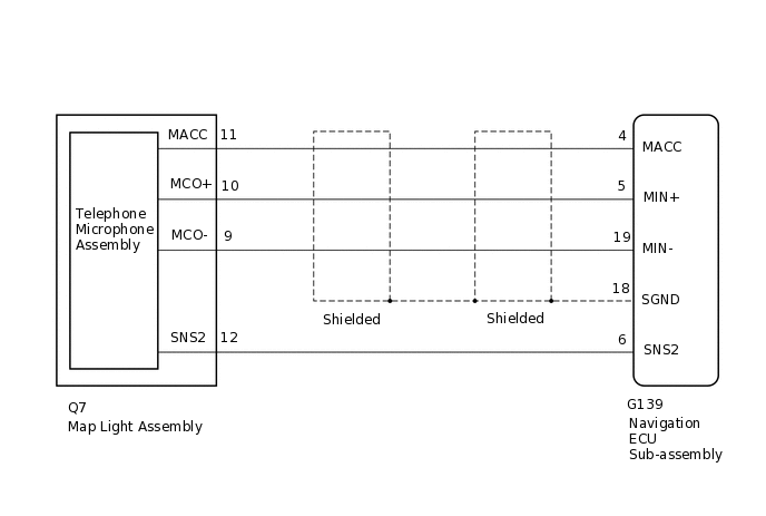
The navigation ECU sub-assembly and map light assembly (telephone microphone assembly) are connected to each other using the microphone connection detection signal lines.
Using this circuit, the navigation ECU sub-assembly sends power to the map light assembly (telephone microphone assembly), and the map light assembly (telephone microphone assembly) sends microphone signals to the navigation ECU sub-assembly.
WIRING DIAGRAM
PROCEDURE
CHECK HARNESS AND CONNECTOR (NAVIGATION ECU SUB-ASSEMBLY - MAP LIGHT ASSEMBLY [TELEPHONE MICROPHONE ASSEMBLY])
Disconnect the G139 navigation ECU sub-assembly connector.
Disconnect the Q7 map light assembly (telephone microphone assembly) connector.
Measure the resistance according to the value(s) in the table below.
Standard Resistance
Tester Connection
Condition
Specified Condition
G139-4 (MACC) - Q7-11 (MACC)
Always
Below 1 Ω
G139-5 (MIN+) - Q7-10 (MCO+)
Always
Below 1 Ω
G139-19 (MIN-) - Q7-9 (MCO-)
Always
Below 1 Ω
G139-6 (SNS2) - Q7-12 (SNS2)
Always
Below 1 Ω
G139-4 (MACC) - Body ground
Always
10 kΩ or higher
G139-5 (MIN+) - Body ground
Always
10 kΩ or higher
G139-19 (MIN-) - Body ground
Always
10 kΩ or higher
G139-18 (SGND) - Body ground
Always
10 kΩ or higher
G139-6 (SNS2) - Body ground
Always
10 kΩ or higher
Result
Proceed to
OK
NG
NG REPAIR OR REPLACE HARNESS OR CONNECTOR
INSPECT NAVIGATION ECU SUB-ASSEMBLY
-
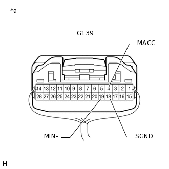
*a
Component with harness connected
(Navigation ECU Sub-assembly)
Measure the resistance according to the value(s) in the table below.
Standard Resistance
Tester Connection
Condition
Specified Condition
G139-18 (SGND) - Body ground
Always
Below 1 Ω
G139-19 (MIN-) - Body ground
Always
Below 1 Ω
Measure the voltage according to the value(s) in the table below.
Standard Voltage
Tester Connection
Switch Condition
Specified Condition
G139-4 (MACC) - Body ground
Engine switch on (ACC)
4 to 6 V
Result
Proceed to
OK
NG
-
INSPECT MAP LIGHT ASSEMBLY (TELEPHONE MICROPHONE ASSEMBLY)
-
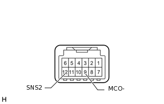
Remove the map light assembly (telephone microphone assembly).
Measure the resistance according to the value(s) in the table below.
Standard Resistance
Tester Connection
Condition
Specified Condition
12 (SNS2) - 9 (MCO-)
Always
Below 1 Ω
Result
Proceed to
OK
NG
NG CHECK TELEPHONE MICROPHONE ASSEMBLYClick here
-
CHECK MAP LIGHT ASSEMBLY
-
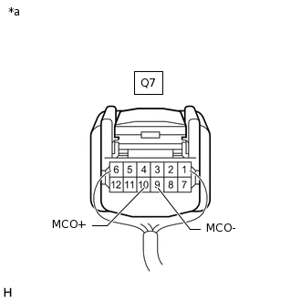
*a
Component with harness connected
(Map Light Assembly)
Remove the map light assembly with its connector still connectoed.
Turn the engine switch on (ACC).
Connect an oscilloscope to terminals 10 (MCO+) and 9 (MCO-) of the map light assembly connector.
Check the waveform of the telephone microphone assembly using the oscilloscope.
Result
Result
Proceed to
A waveform synchronized with the voice input to the map light assembly is output
A
A waveform synchronized with the voice input to the map light assembly is not output
B
-
CHECK TELEPHONE MICROPHONE ASSEMBLY
Replace the telephone microphone assembly with a new or normally functioning one.
Check if the same problem occurs again.
Result
Proceed to
Malfunction disappears
Malfunction does not disappear
Malfunction disappears END (TELEPHONE MICROPHONE ASSEMBLY IS DEFECTIVE)
CHECK MAP LIGHT ASSEMBLY
Replace the map light assembly with a new or normally functioning one.
Check if the same problem occurs again.
Result
Proceed to
Malfunction disappears
Malfunction does not disappear
Malfunction disappears END (MAP LIGHT ASSEMBLY IS DEFECTIVE)
Malfunction does not disappear PROCEED TO NEXT SUSPECTED AREA SHOWN IN PROBLEM SYMPTOMS TABLE
CHECK TELEPHONE MICROPHONE ASSEMBLY
Replace the telephone microphone assembly with a new or normally functioning one.
Check if the same problem occurs again.
Result
Proceed to
Malfunction disappears
Malfunction does not disappear
Malfunction disappears END (TELEPHONE MICROPHONE ASSEMBLY IS DEFECTIVE)