FUEL TANK INSTALLATION
PROCEDURE
INSTALL NO. 1 CHARCOAL CANISTER OUTLET HOSE
-
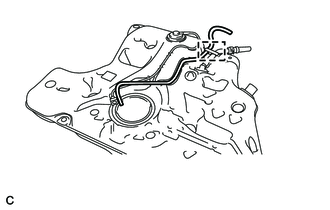
Install the No. 1 charcoal canister outlet hose to the fuel tank assembly.
Connect the No. 1 charcoal canister outlet hose with the clamp.
-
INSTALL NO. 1 FUEL EVAPORATION TUBE SUB-ASSEMBLY
-
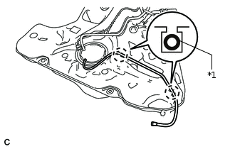
*1
No. 1 Fuel Evaporation Tube Sub-assembly
Engage the 2 claws to install the No. 1 fuel evaporation tube sub-assembly to the fuel tank assembly.
-
INSTALL FUEL TANK MAIN TUBE SUB-ASSEMBLY
-
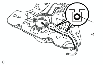
*1
Fuel Tank Main Tube Sub-assembly
Engage the 2 claws to install the fuel tank main tube sub-assembly to the fuel tank assembly.
Tip:After installing the fuel tank main tube sub-assembly and No. 1 fuel evaporation tube sub-assembly, check that the fuel tank main tube sub-assembly is positioned above the No. 1 fuel evaporation tube sub-assembly.
-
INSTALL NO. 4 FUEL TANK CUSHION
Install a new No. 4 fuel tank cushion to the fuel tank assembly.
INSTALL NO. 2 FUEL TANK CUSHION
-
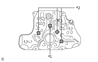
*1
No. 1 Fuel Tank Cushion
*2
No. 2 Fuel Tank Cushion
Install 3 new No. 2 fuel tank cushions as shown in the illustration.
-
INSTALL NO. 1 FUEL TANK CUSHION
Install a new No. 1 fuel tank cushion as shown in the illustration.
INSTALL FUEL TANK ASSEMBLY
Support the fuel tank assembly using an engine lifter.
Raise the engine lifter, then set the fuel tank assembly to the vehicle.
Note:Do not drop the fuel tank assembly.
When installing the fuel tank assembly, tilt it slightly to prevent it from interfering with the suspension arm or other surrounding parts.
Temporarily install the fuel tank assembly with the 4 bolts.
-
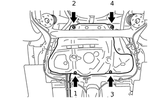
Tighten the 4 bolts in the order shown in the illustration.
39.2 N*m
400 kgf*cm
29 ft.*lbf
Connect the parking brake cable assembly with the 2 bolts.
6.0 N*m
61 kgf*cm
53 in.*lbf
CONNECT FUEL TANK MAIN TUBE SUB-ASSEMBLY
Type A:
-
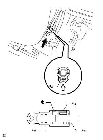
*a
Retainer
*b
Fuel Tube Connector
*c
Fuel Pipe
*d
O-ring

Push

Push In
Push the fuel tube connector onto the fuel pipe and push in the retainer so that the claws engage.
Note:Check that there are no scratches or foreign matter around the connecting parts of the fuel tube connector and fuel pipe before performing this work.
After connecting the fuel tube connector, check that the fuel tube connector is securely connected by pulling on it.
-
-
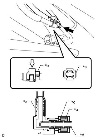
*a
Retainer
*b
Fuel Tube Connector Cover
*c
Fuel Tube Connector
*d
Fuel Pipe
*e
Nylon Tube
*f
O-ring
Type B:
Align the fuel tube connector with the pipe, push the fuel tube connector in until the retainer makes a "click" sound, then engage the lock of the fuel tube connector cover.
Note:Check that there are no scratches or foreign matter around the connecting parts of the fuel tube connector and fuel pipe before starting this step.
After connecting the fuel tube connector, check that the fuel tube connector is securely connected by pulling on it.
CONNECT NO. 1 FUEL EVAPORATION TUBE SUB-ASSEMBLY
-
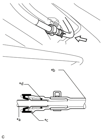
*a
Fuel Pipe
*b
Rubber Hose
*c
Retainer
*d
O-ring
Align the No. 1 fuel evaporation tube sub-assembly with the fuel pipe, then push in the No. 1 fuel evaporation tube sub-assembly until the retainer makes a "click" sound.
Note:Check that there are no scratches or foreign matter around the connecting parts of the fuel tube connector and fuel pipe before performing this work.
After connecting the fuel tube connector, check that the fuel tube connector is securely connected by pulling on it.
-
CONNECT FUEL TANK TO FILLER PIPE HOSE
-
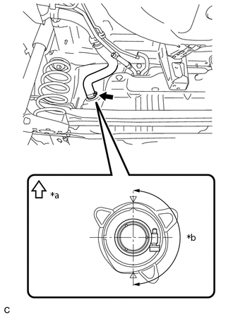
*a
Upper
*b
180°
(Clamp Bolt Area)
Connect the fuel tank to filler pipe hose to the fuel tank assembly and tighten the clamp to secure it.
Tip:Make sure the clamp bolt is within the area shown in the illustration.
-
CONNECT FUEL TANK BREATHER TUBE
-
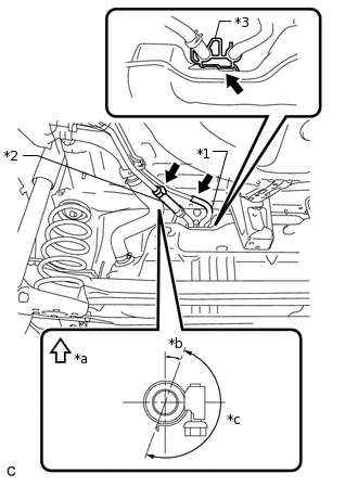
*1
No. 1 Charcoal Canister Outlet Hose
*2
Fuel Tank Breather Tube
*3
Evaporation Vent Tube Clamp
*a
Upper
*b
20°
*c
180°
(Clamp Bolt Area)
Connect the fuel tank breather tube to the fuel tank filler pipe sub-assembly as shown in the illustration and tighten the clamp to secure it.
Tip:Make sure the clamp bolt is within the area shown in the illustration.
-
CONNECT NO. 1 CHARCOAL CANISTER OUTLET HOSE
Connect the No. 1 charcoal canister outlet hose to the fuel tank filler pipe sub-assembly.
Note:After connecting the fuel tank breather tube and No. 1 charcoal canister outlet hose, check that the evaporation vent tube clamp is securely connected to the fuel tank assembly.
INSTALL NO. 1 FUEL TANK PROTECTOR
Temporarily install the No. 1 fuel tank protector with the 3 bolts and nut.
-
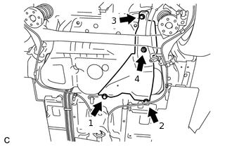
Tighten the 3 bolts and nut in the order shown in the illustration.
5.5 N*m
56 kgf*cm
49 in.*lbf
INSTALL REAR NO. 1 FLOOR UNDER COVER (w/ Cover)
Install the rear No. 1 floor under cover with the 2 grommets.
Install the 4 clips and nut.
INSTALL CENTER EXHAUST PIPE ASSEMBLY
INSTALL REAR FLOOR SIDE MEMBER BRACE SUB-ASSEMBLY
INSTALL REAR FLOOR SIDE MEMBER COVER LH (w/ Cover)
INSTALL REAR FLOOR SIDE MEMBER COVER RH (w/ Cover)
INSTALL FUEL SUCTION TUBE WITH PUMP AND GAUGE ASSEMBLY