CYLINDER BLOCK DISASSEMBLY
PROCEDURE
INSPECT CONNECTING ROD OIL CLEARANCE
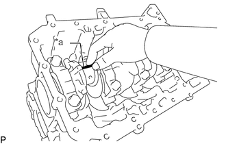
Using an E12 "TORX" socket wrench, remove the 2 connecting rod cap bolts.
Note:Incorrect installation may result in damage to the connecting rod and crankshaft.
Tip:Make sure to place paint marks before disassembly.
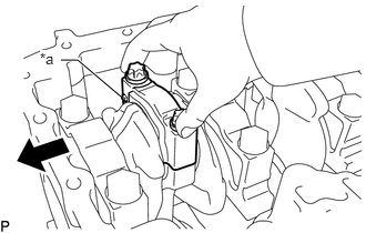
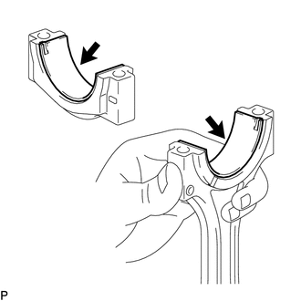
Using the 2 removed connecting rod cap bolts, remove the connecting rod cap and connecting rod bearing by wiggling the connecting rod cap right and left.
Tip:Keep the connecting rod bearing inserted into the connecting rod cap.
Clean the crank pin and connecting rod bearing.
Check the crank pin and connecting rod bearing for pitting and scratches.
-
Lay a strip of Plastigage on the crank pin.
Table 1. Text in Illustration *a
Plastigage
-
Check that the front mark (Mark F) of the connecting rod cap is facing forward and install the connecting rod cap.
Note:Make sure that the surface of the fractured connecting rod does not have foreign matter or become damaged.
Do not contact the surface of the fractured connecting rod wearing gloves.
Table 2. Text in Illustration *a
Front Mark (Mark F)

Front
Using an E12 "TORX" socket wrench, install and alternately tighten the connecting rod bolts of the connecting rod cap in several steps.
20 N*m
204 kgf*cm
15 ft.*lbf
Note:Do not turn the crankshaft assembly.
Mark the front side of each connecting rod cap bolts with paint.
Tighten the cap bolts by 70°.
Note:Do not turn the crankshaft assembly.
Remove the 2 connecting rod cap bolts.
Using the 2 removed connecting rod cap bolts, remove the connecting rod cap and lower bearing by wiggling the connecting rod cap right and left.
Tip:Keep the lower bearing inserted into the connecting rod cap.
-
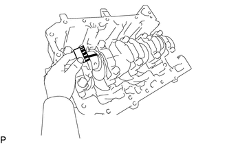
Measure the Plastigage at its widest point.
Standard oil clearance
0.015 to 0.050 mm (0.000945 to 0.00196 in.)
Standard Connecting Rod Bearing Journal
Item
Specified Condition
STD
44.991 to 44.975 mm (1.7771 to 1.7706 in.)
U/S 0.25
44.741 to 44.725 mm (1.7614 to 1.7608 in.)
U/S 0.50
44.491 to 44.475 mm (1.7516 to 1.7509 in.)
Completely remove the Plastigage.
REMOVE PISTON SUB-ASSEMBLY WITH CONNECTING ROD SUB-ASSEMBLY
-
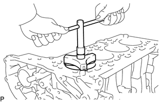
Using a ridge reamer, remove all the carbon from the top of the cylinder.
Using an E12 "TORX" socket wrench, remove the 2 connecting rod bolts.
Note:Incorrect installation may result in damage to the connecting rod and crankshaft.
Tip:Make sure to place paint marks before disassembly.
Remove the connecting rod cap with connecting rod bearing.
Push out the piston and connecting rod with connecting rod bearing through the top of the cylinder block to remove them.
Tip:Arrange the piston sub-assembly and connecting rod sub-assemblies in the correct order.
-
REMOVE CONNECTING ROD BEARING
-
Remove the connecting rod bearings.
Note:Make sure that the surface of the fractured connecting rod does not have foreign matter or become damaged.
Do not contact the surface of the fractured connecting rod wearing gloves.
Tip:Arrange the removed parts in the correct order.
-
REMOVE PISTON RING SET
Tip:Arrange the piston rings in the correct order.
-
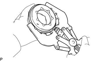
Using a piston ring expander, remove the No. 1 and No. 2 compression rings.
Using a piston ring expander, remove the oil ring rail.
Remove the oil ring expander by hand.
-
REMOVE PISTON WITH PIN SUB-ASSEMBLY
Check the fitting condition between the piston and piston pin by trying to move the piston back and forth on the piston pin.
If any movement is felt, replace the piston with pin sub-assembly.
-
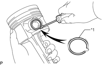
Using a screwdriver, pry out the 2 snap rings.
Table 3. Text in Illustration *1
Snap Ring
Remove the piston pin from the piston and connecting rod.
Tip:The piston and pin are a matched set.
Arrange the pistons, pins, rings, connecting rods and bearings in the correct order.
INSPECT CRANKSHAFT THRUST CLEARANCE
-
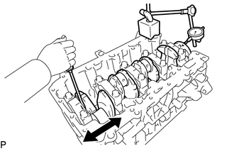
Using a dial indicator, measure the thrust clearance while prying the crankshaft back and forth with a screwdriver.
Standard thrust clearance
0.06 to 0.25 mm (0.00236 to 0.00984 in.)
Standard No. 3 Crankshaft Bearing Thickness
Item
Specified Condition
STD
25.02 to 25.53 mm (0.985 to 1.005 in.)
O/S 0.20
25.22 to 25.73 mm (0.992 to 1.012 in.)
O/S 0.40
25.42 to 25.93 mm (1.000 to 1.020 in.)
-
REMOVE CRANKSHAFT ASSEMBLY
-
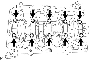
Uniformly loosen and remove the 10 bearing cap bolts in several steps in the sequence shown in the illustration.
Note:Do not reuse the bearing cap bolt.
Remove the crankshaft assembly.
-
REMOVE CRANKSHAFT BEARING
Tip:Keep the upper and lower crankshaft bearing and crankshaft bearing cap as a set.
Arrange the crankshaft bearing cap and bearings in the correct order.
-
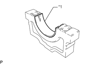
Remove the 4 lower crankshaft bearings.
Table 4. Text in Illustration *1
Lower Crankshaft Bearing
Remove the No. 3 lower crankshaft bearing.
Remove the 4 upper crankshaft bearings.
-
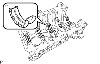
Remove the No. 3 upper crankshaft bearings.
Table 5. Text in Illustration *1
No. 3 Upper Crankshaft Bearing
REMOVE NO. 1 OIL NOZZLE SUB-ASSEMBLY
-
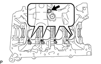
Using a 5 mm hexagon wrench, remove the 4 bolts and 4 No. 1 oil nozzle sub-assemblies.
-