REAR LOWER ARM INSTALLATION

CAUTION / NOTICE / HINT
Tech Tips
-
Use the same procedure for the RH and LH sides.
-
The procedure listed below is for the LH side.
PROCEDURE
-
INSTALL REAR NO. 1 SPRING BUMPER LH
-
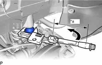
*a Torque Wrench Fulcrum Length Using SST, install the rear No. 1 spring bumper LH.
- SST
- 09922-10010
- Torque:
- Specified tightening torque
- 30 N*m { 306 kgf*cm, 22 ft.*lbf }
Tech Tips
-
Calculate the torque wrench reading when changing the fulcrum length of the torque wrench.
-
When using SST (fulcrum length of 116.5 mm (4.5866 in.)) + torque wrench (fulcrum length of 180 mm (7.0866 in.)): 18.2 N*m (186 kgf*cm, 13 ft.*lbf)
-
-
TEMPORARILY INSTALL REAR NO. 2 SUSPENSION ARM ASSEMBLY LH
-
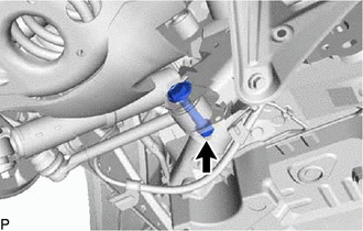
Temporarily install the rear No. 2 suspension arm to the suspension member with the bolt and nut.
Note
Since a stopper nut is used, tighten the bolt.
Tech Tips
Insert the bolt from the rear of the vehicle.
-
-
INSTALL REAR UPPER COIL SPRING INSULATOR LH
-
INSTALL REAR LOWER COIL SPRING INSULATOR LH
-
INSTALL REAR COIL SPRING LH
-
INSTALL REAR STABILIZER LINK ASSEMBLY LH
-
TEMPORARILY INSTALL REAR NO. 1 SUSPENSION ARM ASSEMBLY LH
-
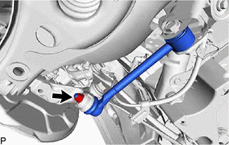
Temporarily install the rear No. 1 suspension arm to the rear axle carrier with a new nut.
-
Insert the rear suspension toe adjust cam sub-assembly from the rear of the vehicle to install the rear No. 1 suspension arm assembly LH, and then temporarily install the No. 2 camber adjust cam with the nut.
-
-
TEMPORARILY INSTALL REAR SHOCK ABSORBER ASSEMBLY LH
-
STABILIZE SUSPENSION
-
TIGHTEN REAR NO. 2 SUSPENSION ARM ASSEMBLY LH
-
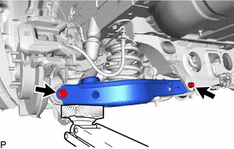
Tighten the 2 bolts and nut of the rear No. 2 suspension arm assembly.
- Torque:
- 90 N*m { 918 kgf*cm, 66 ft.*lbf }
Note
Since a stopper nut is used, tighten the bolt.
-
-
TIGHTEN REAR SHOCK ABSORBER ASSEMBLY LH
-
TIGHTEN REAR NO. 1 SUSPENSION ARM ASSEMBLY LH
-
Tighten the nut.
- Torque:
- 100 N*m { 1020 kgf*cm, 74 ft.*lbf }
-
Tighten the nut of the rear No. 1 suspension arm.
- Torque:
- 120 N*m { 1224 kgf*cm, 89 ft.*lbf }
Note
Align the matchmarks on the rear suspension member and adjust cam.
-
-
INSTALL REAR HEIGHT CONTROL SENSOR SUB-ASSEMBLY LH
-
INSTALL REAR SUSPENSION ARM COVER LH
-
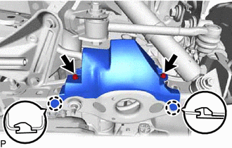
Insert the 2 claws of the rear suspension arm cover LH into the rear No. 2 suspension arm assembly LH.
-
Install the rear suspension arm cover LH with the 2 bolts.
- Torque:
- 12 N*m { 122 kgf*cm, 9 ft.*lbf }
Note
Make sure that the 2 claws of the rear suspension arm cover are inserted.
-
-
INSTALL REAR WHEEL
-
INSPECT AND ADJUST REAR WHEEL ALIGNMENT
-
HEIGHT CONTROL SENSOR SIGNAL INITIALIZATION
-
PERFORM INITIALIZATION