LANE DEPARTURE ALERT SYSTEM(w/ Steering Control) Main Switch Circuit
| DTC Code | DTC Name |
|---|---|
| Main Switch Circuit |
DESCRIPTION
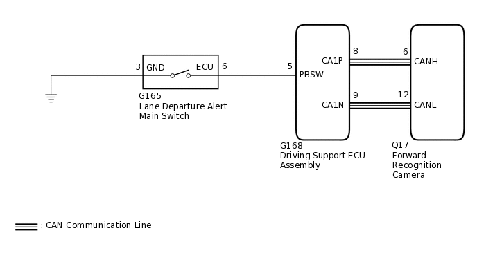
The driving support ECU assembly receives a lane departure alert main switch signal from the lane departure alert main switch and sends the signal to the forward recognition camera via CAN communication.
WIRING DIAGRAM
PROCEDURE
READ VALUE USING GTS (CAN BUS CHECK)
Connect the GTS to the DLC3.
Turn the power switch on (IG).
Turn the GTS on.
Enter the following menus: System Select / Can Bus Check.
CAN Bus Check
Result
Result
Proceed to
All of the ECUs and sensors that are currently connected to the CAN communication system are displayed.
A
None of the ECUs and sensors that are currently connected to the CAN communication system are displayed, or some of them are not displayed.
B
CHECK DTC (HEALTH CHECK)
Connect the GTS to the DLC3.
Turn the power switch on (IG).
Turn the GTS on.
Enter the following menus: System Select / Health Check.
Check DTCs.
Result
Result
Proceed to
No DTCs are output.
A
DTCs are output.
B
B GO TO DTC CHART
INSPECT LANE DEPARTURE ALERT MAIN SWITCH
Remove the lane departure alert main switch.
for LHD
for RHD
Inspect the lane departure alert main switch.
for LHD
for RHD
Result
Proceed to
OK
NG
CHECK HARNESS AND CONNECTOR (LANE DEPARTURE ALERT MAIN SWITCH - DRIVING SUPPORT ECU ASSEMBLY AND BODY GROUND)
Disconnect the G165 lane departure alert main switch connector.
Disconnect the G168 driving support ECU assembly connector.
Measure the resistance according to the value(s) in the table below.
Standard Resistance
Tester Connection
Condition
Specified Condition
G165-6 (ECU) - G168-5 (PBSW)
Always
Below 1 Ω
G165-6 (ECU) or G168-5 (PBSW) - Body ground
Always
10 kΩ or higher
G165-3 (GND) - Body ground
Always
Below 1 Ω
Result
Proceed to
OK
NG
NG REPAIR OR REPLACE HARNESS OR CONNECTOR