G-BOOK SYSTEM(w/ Telematics Transceiver) Received Voice Signal Circuit
| DTC Code | DTC Name |
|---|---|
| Received Voice Signal Circuit |
WIRING DIAGRAM
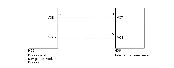
CAUTION / NOTICE / HINT
When replacing the display and navigation module display or the telematics transceiver, perform the vehicle contract setting (Click here).
PROCEDURE
CHECK HARNESS AND CONNECTOR (DISPLAY AND NAVIGATION MODULE DISPLAY - TELEMATICS TRANSCEIVER)
Disconnect the H35 display and navigation module display connector.
Disconnect the H36 telematics transceiver connector.
Measure the resistance according to the value(s) in the table below.
Standard Resistance
Tester Connection
Condition
Specified Condition
H35-7 (VOR+) - H36-3 (VOT+)
Always
Below 1 Ω
H35-6 (VOR-) - H36-5 (VOT-)
Always
Below 1 Ω
H35-7 (VOR+) - Body ground
Always
10 kΩ or higher
H35-6 (VOR-) - Body ground
Always
10 kΩ or higher
Result
Result
OK
NG
NG REPAIR OR REPLACE HARNESS OR CONNECTOR
CHECK TELEMATICS TRANSCEIVER
-
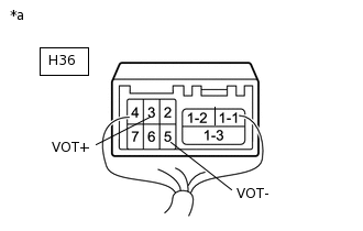
*a
Component with harness connected
(Telematics Transceiver)
Check the waveforms according to the value(s) in the table below.
OK
Tester Connection
Condition
Specified Condition
H36-3 (VOT+) - Body ground
Receiving call using operator service
Waveform synchronized with received voice is output
H36-5 (VOT-) - Body ground
Receiving call using operator service
Waveform synchronized with received voice is output
Result
Result
OK
NG
-