ECD SYSTEM, Diagnostic DTC:P040C and P040D
| DTC Code | DTC Name |
|---|---|
| P040C | Exhaust Gas Recirculation Temperature Sensor "A" Circuit Low |
| P040D | Exhaust Gas Recirculation Temperature Sensor "A" Circuit High |
DESCRIPTION
The EGR gas temperature sensor is located on the EGR cooler.
The EGR gas temperature sensor is required for the exact control of the exhaust gas recirculation.
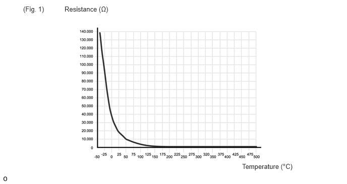
A thermistor built into the sensor changes its resistance value according to the exhaust gas recirculation temperature. The lower the exhaust gas recirculation temperature, the greater the thermistor resistance value. The higher the exhaust gas recirculation temperature, the lower the thermistor resistance value.
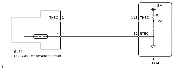
The EGR gas temperature sensor is connected to the ECM. The 5 V power source voltage in the ECM is applied to the EGR gas temperature sensor from terminal THEC via resistor R.
The resistor R and the EGR gas temperature sensor are connected in series. When the resistance value of the EGR gas temperature sensor changes in accordance with changes in the exhaust gas recirculation gas temperature, the voltage at terminal THEC also changes.
The resistance is temperature dependent and varies between 138 kΩ and 127 Ω, which corresponds to a temperature of -50°C (-58°F) to 500°C (932°F) (See Fig. 1).
DTC No. |
Detection Item |
DTC Detection Condition |
Trouble Area |
MIL |
Memory |
|---|---|---|---|---|---|
P040C |
Exhaust Gas Recirculation Temperature Sensor "A" Circuit Low |
EGR gas temperature sensor output voltage is 0.2 V or less for 0.6 seconds. (3 trip detection logic) |
|
Comes on |
DTC stored |
P040D |
Exhaust Gas Recirculation Temperature Sensor "A" Circuit High |
EGR gas temperature sensor output voltage is 4.98 V or more for 0.6 seconds. (3 trip detection logic) |
|
Comes on |
DTC stored |
DTC No. |
Data List |
|---|---|
P040C P040D |
Temperature Down Stream of EGR Cooler |
WIRING DIAGRAM
CAUTION / NOTICE / HINT
When the ECM must be replaced, before replacing the ECM, perform the "Learning Values Save" function using the GTS. Then after installing the new ECM, perform all of the initialization/registrations for the "Learning Values Write" function by following the instructions shown on the GTS display.
Read freeze frame data using the GTS. Freeze frame data records the engine condition when malfunctions are detected. When troubleshooting, freeze frame data can help determine if the vehicle was moving or stationary, if the engine was warmed up or not, and other data from the time the malfunction occurred.
PROCEDURE
CHECK HARNESS AND CONNECTOR (EGR GAS TEMPERATURE SENSOR - ECM)
Disconnect the EGR gas temperature sensor connector.
Disconnect the ECM connector.
Measure the resistance according to the value(s) in the table below.
Standard Resistance
Tester Connection
Condition
Specified Condition
B132-1 (THEC) - B112-118 (THEC)
Always
Below 1 Ω
B132-2 (E2) - B112-86 (ETEC)
Always
Below 1 Ω
B132-1 (THEC) or B112-118 (THEC) - Body ground
Always
10 kΩ or higher
Result
Proceed to
OK
NG
NG REPAIR OR REPLACE HARNESS OR CONNECTORClick here
INSPECT EGR GAS TEMPERATURE SENSOR
Inspect the EGR gas temperature sensor.
Result
Proceed to
OK
NG
NG REPLACE EGR GAS TEMPERATURE SENSORClick here
REPLACE ECM
Replace the ECM.
Result
Proceed to
NEXT
NEXT CONFIRM WHETHER MALFUNCTION HAS BEEN SUCCESSFULLY REPAIREDClick here
REPLACE EGR GAS TEMPERATURE SENSOR
Replace the EGR gas temperature sensor.
Result
Proceed to
NEXT
NEXT CONFIRM WHETHER MALFUNCTION HAS BEEN SUCCESSFULLY REPAIREDClick here
REPAIR OR REPLACE HARNESS OR CONNECTOR
Repair or replace the harness or connector.
Result
Proceed to
NEXT
CONFIRM WHETHER MALFUNCTION HAS BEEN SUCCESSFULLY REPAIRED
Connect the GTS to the DLC3.
Turn the ignition switch to ON and turn the GTS on.
Clear the DTCs.
Powertrain > Engine and ECT > Clear DTCs
Turn the ignition switch off and wait for 60 seconds or more [A].
Perform road test [B].
Repeat [A] and [B] for the number of trips detected.
Enter the following menus: Powertrain / Engine and ECT / Trouble Codes.
Powertrain > Engine and ECT > Trouble Codes
Confirm that the DTC is not output again.
Result
Proceed to
NEXT
NEXT END