TIMING CHAIN INSTALLATION

-
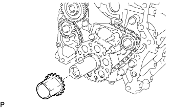
INSTALL NO.2 CHAIN SUB-ASSEMBLY
-
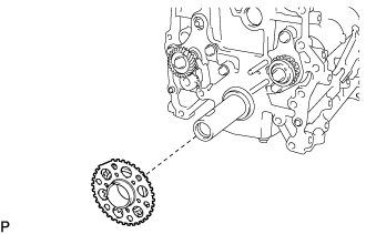
Install the crankshaft timing sprocket No.2 to the crankshaft.
-
Check that the No.1 cylinder is at TDC and that the weights of the balance shaft No.1 and No.2 are at the bottom side.
-
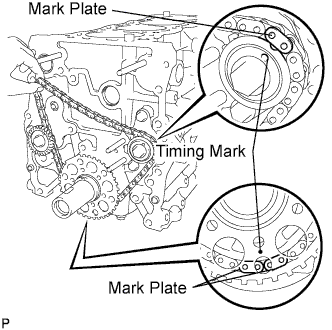
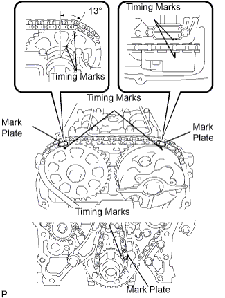
Install the No.2 chain by matching its mark plate with the timing marks on the crankshaft timing sprocket and balance shaft timing sprocket.
-
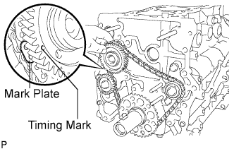
Fit the other timing mark (yellow) of the crankshaft timing sprocket behind the timing mark (large) of the balance shaft drive gear.
-
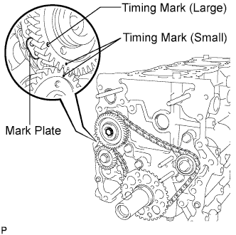
Insert the balance shaft drive gear shaft through the balance shaft drive gear so that it fits into the thread hole, then align the small timing mark of the balance shaft drive gear with the timing mark of the balance shaft timing gear (large), install the bolt to the balance shaft drive gear and tighten it.
- Torque:
- 25 N*m { 255 kgf*cm, 18 ft.*lbf }
-
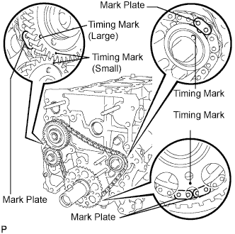
Check that each timing mark is matched with the corresponding mark link.
Note
Check that the No.1 cylinder is at TDC and that the wights of the balance shaft No.1 and No.2 are at the bottom side.
-
-
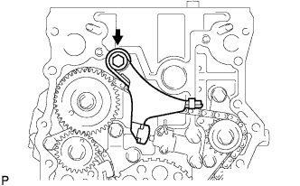
INSTALL CHAIN TENSIONER ASSEMBLY NO.2
-
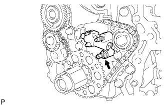
Install the chain tensioner assembly No.2 with the nut.
- Torque:
- 18 N*m { 184 kgf*cm, 13 ft.*lbf }
-
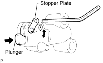
Assemble the chain tensioner with the hexagon wrench (width 1.5 mm) installed.
-
-
INSTALL CHAIN VIBRATION DAMPER NO.3
-
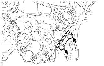
Install the chain vibration damper No.3 with the 2 bolts.
- Torque:
- 18 N*m { 184 kgf*cm, 13 ft.*lbf }
-
-
INSTALL CHAIN VIBRATION DAMPER NO.2
-
Install the chain vibration damper No.2 with the bolt.
- Torque:
- 27 N*m { 270 kgf*cm, 20 ft.*lbf }
-
-
INSTALL CRANKSHAFT TIMING GEAR OR SPROCKET
-
Install the crankshaft timing gear to the crankshaft.
-
-
INSTALL CHAIN VIBRATION DAMPER NO.1
-
Install the vibration damper with the bolt and nut.
- Torque:
- for bolt
- 21 N*m { 214 kgf*cm, 15 ft.*lbf }
- for nut
- 18 N*m { 184 kgf*cm, 13 ft.*lbf }
-
Remove the hexagon wrench from the chain tensioner and release the plunger.
-
-
INSTALL CHAIN SUB-ASSEMBLY
-
As shown in the illustration, install the chain on the sprocket and gear with the painted marks aligned with the timing marks on the sprocket and gear.
Tech Tips
-
The camshaft mark plate is orange.
-
The crankshaft mark plate is yellow.
-
-
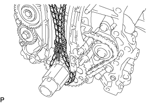
Use a rope to tie the chain of the crankshaft timing sprocket. Tie the rope near the gear.
Note
After the chain tensioner has been installed, the rope must be removed.
Tech Tips
The rope is tied so that the chain will not jump a tooth.
-
-
INSTALL CHAIN TENSIONER SLIPPER
-
Install the tensioner slipper with the bolt.
- Torque:
- 21 N*m { 214 kgf*cm, 15 ft.*lbf }
-
-
INSTALL CHAIN TENSIONER ASSEMBLY NO.1
-
Install a new gasket and the chain tensioner No.1 with the bolt and nut.
- Torque:
- 10 N*m { 102 kgf*cm, 7 ft.*lbf }
Note
Remove the hexagon wrench after installing the timing chain guide.
-
-
INSTALL TIMING CHAIN GUIDE
-
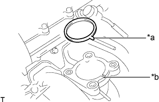
Install a new O-ring and the chain guide with the 2 bolts.
- Torque:
- 10 N*m { 102 kgf*cm, 7 ft.*lbf }
-
Remove the hexagon wrench from the chain tensioner and release the plunger.
-
-
INSTALL TIMING GEAR CASE OR TIMING CHAIN CASE OIL SEAL
-
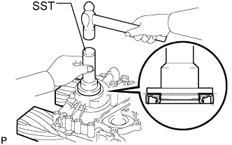
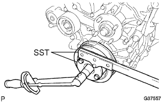
Place the timing chain cover on wooden blocks.
-
Using SST, tap in a new oil seal until its surface is flush with the timing gear case edge.
- SST
- 09223-50010
Note
-
Keep the lip free from foreign matter.
-
Do not tap the oil seal at an angle.
-
-
INSTALL TIMING CHAIN OR BELT COVER SUB-ASSEMBLY
-
INSTALL OIL STRAINER SUB-ASSEMBLY
-
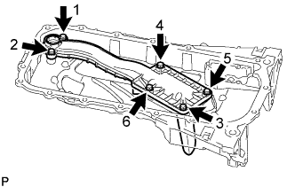
Install the oil strainer sub-assembly with the 6 bolts, and tighten the 6 bolts in the sequence shown in the illustration.
- Torque:
- 10 N*m { 102 kgf*cm, 7 ft.*lbf }
-
-
INSTALL OIL PAN SUB-ASSEMBLY
-
Install the stud bolt.
-
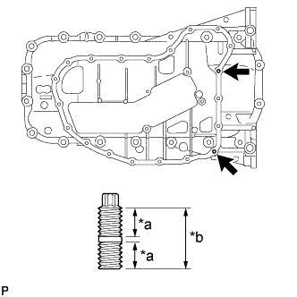
Text in Illustration *a 9.0 mm (0.354 in.) *b 19.0 mm (0.748 in.) Using an E6 "torx" socket wrench, install the stud bolts.
- Torque:
- 3.0 N*m { 31 kgf*cm, 27 in.*lbf }
-
-
Remove any old packing (FIPG material) and be careful not to drop any oil on the contact surfaces of the cylinder block sub-assembly and oil pan sub-assembly.
-
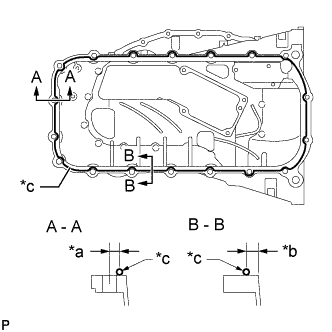
Text in Illustration *a 8.0 mm (0.315 in.) *b 6.5 mm (0.256 in.) *c Seal Packing Apply seal packing as shown in the illustration.
Seal packing Toyota Genuine Seal Packing Black, Three Bond 1207B or equivalent Standard seal diameter 2.0 to 3.0 mm (0.0787 to 0.118 in.) Note
-
Install the oil pan sub-assembly within 3 minutes and tighten the bolts within 15 minutes after applying seal packing.
-
Do not add the engine oil for at least 4 hours after the installation.
-
Do not start the engine for at least 4 hours after the installation.
-
-
Install a new gasket to the oil strainer sub-assembly.
-
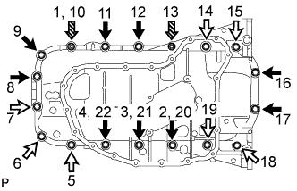
Install the oil pan sub-assembly with the 16 bolts and 2 nuts, and tighten the 16 bolts and 2 nuts in the sequence shown in the illustration.
- Torque:
- 26 N*m { 265 kgf*cm, 19 ft.*lbf }
Bolt Length Item Length Bolt A 20 mm (0.787 in.) Bolt B 40 mm (1.57 in.) Text in Illustration 
Bolt A 
Bolt B 
Nut
-
-
INSTALL NO. 2 OIL PAN SUB-ASSEMBLY
-
Remove any old packing (FIPG material) and be careful not to drop any oil on the contact surfaces of the oil pan sub-assembly and No. 2 oil pan sub-assembly.
-
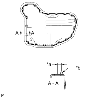
Text in Illustration *a 6.0 mm (0.236 in.) *b Seal Packing Apply seal packing as shown in the illustration.
Seal packing Toyota Genuine Seal Packing Black, Three Bond 1207B or equivalent Standard seal diameter 3.0 to 4.0 mm (0.118 to 0.157 in.) Note
-
Install the No. 2 oil pan sub-assembly within 3 minutes and tighten the bolts within 15 minutes after applying seal packing.
-
Do not add the engine oil for at least 4 hours after the installation.
-
Do not start the engine for at least 4 hours after the installation.
-
-
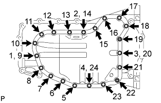
Install the No. 2 oil pan sub-assembly with the 18 bolts and 2 nuts, and tighten the 18 bolts and 2 nuts in the sequence shown in the illustration.
- Torque:
- 9.0 N*m { 92 kgf*cm, 80 in.*lbf }
-
Install a new gasket and the oil pan drain plug.
- Torque:
- 38 N*m { 382 kgf*cm, 28 ft.*lbf }
-
-
INSTALL CRANKSHAFT PULLEY
-
Align the pulley set key with the key groove of the pulley, and slide on the pulley.
-
Using SST, install the crankshaft pulley bolt.
- SST
- 09213-54015 ( 91651-60855 )
- 09330-00021
- Torque:
- 260 N*m { 2,651 kgf*cm, 192 ft.*lbf }
-
-
INSTALL CYLINDER HEAD COVER SUB-ASSEMBLY
-
Install the cylinder head cover gasket and cylinder head gasket No.2 to the cylinder head cover.
-
Remove any old packing (FIPG) material.
-
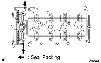
Apply seal packing as shown in the illustration.
Seal packing Toyota Genuine Seal Packing Black, Three Bond 1207B or equivalent Note
-
Remove any oil from the contact surface.
-
Install the cylinder head cover sub-assembly within 3 minutes after applying seal packing.
-
Do not start the engine for at least 4 hours after installing.
-
-
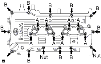
Temporarily install the head cover with the 19 bolts and 2 nuts.
-
Fully tighten the A bolts.
- Torque:
- 9.0 N*m { 92 kgf*cm, 80 in.*lbf }
-
Fully tighten the B bolts and nuts.
- Torque:
- 9.0 N*m { 92 kgf*cm, 80 in.*lbf }
-
Make sure that the A bolts are completely tighten to the specified torque.
- Torque:
- 9.0 N*m { 92 kgf*cm, 80 in.*lbf }
-
Connect the ventilation hose No.1.
-
-
INSTALL IGNITION COIL ASSEMBLY
-
Install the ignition coils with the bolts.
- Torque:
- 9.0 N*m { 92 kgf*cm, 80 in.*lbf }
-
-
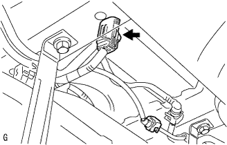
INSTALL AIR PRESSURE SENSOR (w/ Manifold Absolute Pressure Sensor)
-
Install the air pressure sensor with the bolt.
- Torque:
- 5.0 N*m { 51 kgf*cm, 44 in.*lbf }
-
Install the air pressure sensor together with the bracket with the 2 bolts.
- Torque:
- 8.0 N*m { 82 kgf*cm, 71 in.*lbf }
-
Attach the wire harness clamp.
-
Connect the vacuum hose and clamp.
-
Connect the connector.
-
-
INSTALL MANUAL TRANSMISSION UNIT ASSEMBLY (for Manual Transmission)
-
INSTALL AUTOMATIC TRANSMISSION ASSEMBLY (for Automatic Transmission)
-
INSTALL V-RIBBED BELT TENSIONER ASSEMBLY
-
Temporarily install the belt tensioner with the 2 bolts.
Tech Tips
-
Make sure that the belt tensioner is in contact with the engine block.
-
Check that the bolt holes of the belt tensioner and timing chain cover are aligned.
-
-
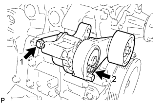
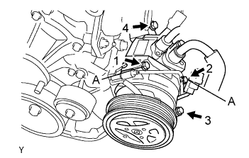
Install the tensioner by tightening the 2 bolts in the order shown in the illustration.
- Torque:
- Bolt 1
- 40 N*m { 408 kgf*cm, 30 ft.*lbf }
- Bolt 2
- 21 N*m { 214 kgf*cm, 15 ft.*lbf }
-
-
INSTALL IDLER PULLEY SUB-ASSEMBLY NO.1
-
Install the idler pulley sub-assembly No.1, collar and pulley plate with the bolt.
- Torque:
- 43 N*m { 438 kgf*cm, 32 ft.*lbf }
Note
Check that the pulley plate and collar are assembled properly to the idler pulley No.1.
-
-
INSTALL COMPRESSOR MOUNTING BRACKET NO.1 (w/ Air Conditioning System)
Note
Install the compressor mounting bracket No. 1 exactly as described in the procedures below to properly secure and prevent damage to the fan and generator V belt.
-
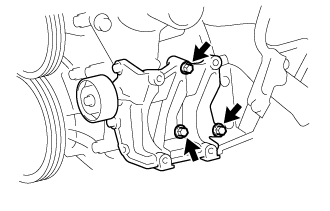
Temporarily install the compressor mounting bracket No. 1 with the 3 bolts.
Tech Tips
Temporarily install the compressor mounting bracket No. 1 with the 3 bolts so that the bracket can be moved by hand.
-
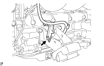
Push the compressor mounting bracket No. 1 toward the cylinder block as shown in the illustration and tighten bolt B.
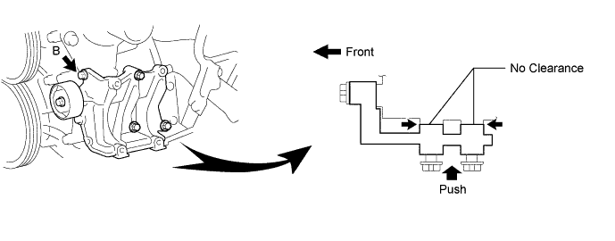
- Torque:
- Bolt B
- 45 N*m { 459 kgf*cm, 33 ft.*lbf }
Tech Tips
Make sure there is no clearance between the cylinder block and compressor mounting bracket No. 1 as shown in the illustration.
-
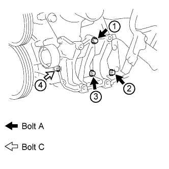
Uniformly tighten the 4 bolts in the order shown in the illustration.
- Torque:
- Bolt A
- 45 N*m { 459 kgf*cm, 33 ft.*lbf }
- Bolt C
- 25 N*m { 255 kgf*cm, 18 ft.*lbf }
-
-
INSTALL GENERATOR ASSEMBLY
-
Install the generator assembly with the 3 bolts.
- Torque:
- 43 N*m { 438 kgf*cm, 32 ft.*lbf }
-
Install the generator wire with the nut to terminal B.
- Torque:
- 9.8 N*m { 100 kgf*cm, 87 in.*lbf }
-
Install the terminal cap.
-
Connect the generator connector.
-
-
INSTALL WATER BY-PASS PIPE NO.1
-
Install a new gasket and the water by-pass pipe with the 2 nuts and bolt.
- Torque:
- Nut
- 18 N*m { 180 kgf*cm, 13 ft.*lbf }
- Bolt
- 8.0 N*m { 80 kgf*cm, 71 in.*lbf }
-
-
INSTALL FAN PULLEY
-
Install the fan spacer and fan pulley with the 4 nuts.
- Torque:
- 25 N*m { 255 kgf*cm, 18 ft.*lbf }
-
-
INSTALL INTAKE MANIFOLD
-
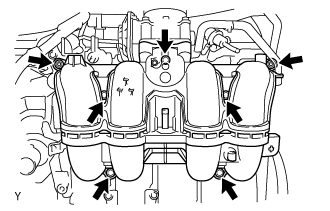
Install a new gasket and the intake manifold with the 5 bolts and 2 nuts.
- Torque:
- 25 N*m { 255 kgf*cm, 18 ft.*lbf }
-
Connect the ventilation hose No.3.
-
-
INSTALL INJECTOR ASSEMBLY
Tech Tips
w/ Dual VVT-i:
Perform "Inspection After Repairs" after replacing the fuel injector assembly Click here.
-
Apply a light coat of gasoline or spindle oil to new O-rings, and then install one onto each fuel injector assembly.
-
Apply a light coat of gasoline or spindle oil to the contact surfaces of the fuel delivery pipe sub-assembly and the O-ring of the fuel injector assembly.
-
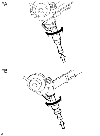
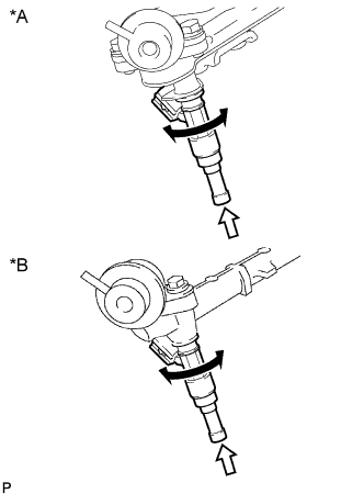
Apply a light coat of gasoline or spindle oil to the O-ring again, and then install the fuel injector assembly into the fuel delivery pipe sub-assembly by turning it right and left.
Text in Illustration *A w/ Dual VVT-i *B w/o Dual VVT-i Turn Push Note
-
Be careful not to twist the O-ring.
-
After installing the fuel injector assembly, check that it turns smoothly. If not, reinstall it with a new O-ring.
-
-
-
INSTALL FUEL DELIVERY PIPE SUB-ASSEMBLY
-
Apply a light coat of gasoline or spindle oil to new O-rings and install them to the injector spacers.
Note
Make sure that the O-rings are installed between the parts correctly.
-
Install the 4 injector spacers to the cylinder head sub-assembly.
-
Install 4 new injector vibration insulators to the cylinder head sub-assembly.
-
Install the 2 No. 1 delivery pipe spacers to the cylinder head sub-assembly.
-
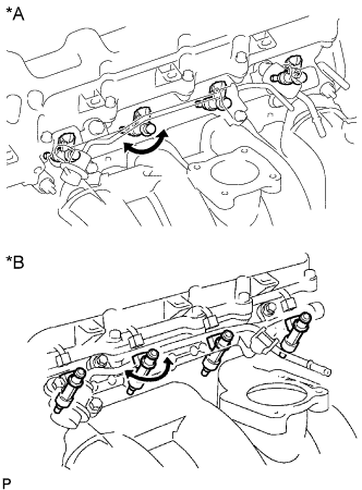
Text in Illustration *A w/ Dual VVT-i *B w/o Dual VVT-i Temporarily install the fuel delivery pipe sub-assembly together with the 4 fuel injector assemblies with the 2 bolts.
Note
-
Do not drop the fuel injector assemblies when installing the fuel delivery pipe sub-assembly.
-
Make sure that the fuel injector assembly turns smoothly.
-
-
Tighten the 2 bolts.
- Torque:
- 12 N*m { 122 kgf*cm, 9 ft.*lbf }
-
Apply a light coat of gasoline or spindle oil to a new O-ring.
-
Install the fuel pressure pulsation damper assembly with the 2 bolts.
- Torque:
- 9.0 N*m { 92 kgf*cm, 80 in.*lbf }
-
Connect the 4 fuel injector connectors.
-
Connect the No. 2 fuel hose to the fuel pressure regulator assembly, and slide the clamp to secure the hose.
-
Connect the vacuum hose to the fuel pressure regulator assembly.
-
-
INSTALL THROTTLE WITH MOTOR BODY ASSEMBLY
Tech Tips
w/ Dual VVT-i:
Perform "Inspection After Repairs" after replacing the throttle body assembly Click here.
-
Text in Illustration *a Protrusion *b Groove Install a new gasket onto the intake manifold.
Tech Tips
Align the protrusion of the gasket with the groove of the intake manifold.
-
Install the throttle body assembly with the 4 bolts.
- Torque:
- 10 N*m { 102 kgf*cm, 7 ft.*lbf }
-
Connect the No. 2 water by-pass hose to the throttle body assembly, and slide the clamp to secure the hose.
-
Connect the water by-pass hose to the throttle body assembly, and slide the clamp to secure the hose.
-
Connect the throttle motor connector.
-
-
CONNECT ENGINE WIRE
-
INSTALL COMPRESSOR AND MAGNETIC CLUTCH (w/ Air Conditioning System)
-
Temporarily install the bolt A to install the compressor.
-
Install the compressor completely by tightening the 4 bolts in the order shown in the illustration.
- Torque:
- 25 N*m { 255 kgf*cm, 18 ft.*lbf }
Note
In order to prevent misalignment, which causes belt rattle, tightening of the bolts must be performed in the order shown.
-
Connect the suction tube clamp with the bolt.
- Torque:
- 5.4 N*m { 55 kgf*cm, 48 in.*lbf }
-
Connect the compressor connector.
-
-
INSTALL OIL LEVEL GAUGE GUIDE
-
Install the gauge guide with the bolt.
- Torque:
- 20 N*m { 204 kgf*cm, 15 ft.*lbf }
-
-
INSTALL OIL LEVEL GAUGE SUB-ASSEMBLY
-
INSTALL VANE PUMP ASSEMBLY
-
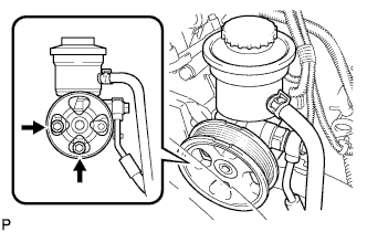
Install the vane pump with the 2 bolts.
- Torque:
- 21 N*m { 214 kgf*cm, 15 ft.*lbf }
-
Connect the PS fluid pressure switch connector.
-
-
CONNECT FUEL HOSE NO.2
-
Connect the fuel hose No.2 to the delivery pipe.
-
-
CONNECT FUEL HOSE
-
Connect the No. 1 fuel hose to the fuel pressure pulsation damper assembly Click here.
-
-
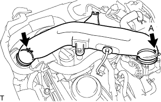
INSTALL INTAKE AIR CONNECTOR
-
Temporarily install the intake air connector to the throttle body assembly.
-
Connect the vacuum hose to the intake air connector.
-
Connect the No. 2 PCV hose to the cylinder head cover sub-assembly, and slide the clamp to secure the hose.
-
Install the intake air connector with the 2 bolts.
- Torque:
- 8.0 N*m { 82 kgf*cm, 71 in.*lbf }
-
Tighten the 2 hose clamps.
- Torque:
- for clamp A
- 5.0 N*m { 51 kgf*cm, 44 in.*lbf }
-
-
CONNECT UNION TO CONNECTOR TUBE HOSE
-
Connect the union to connector tube hose to the intake manifold.
-
-
CONNECT FUEL VAPOR FEED HOSE ASSEMBLY
-
Connect the fuel vapor feed hose to the VSV.
-
-
CONNECT RADIATOR HOSE OUTLET
-
Connect the radiator outlet hose to the clamp.
-
-
CONNECT RADIATOR HOSE INLET
-
Connect the radiator inlet hose to the clamp.
-
-
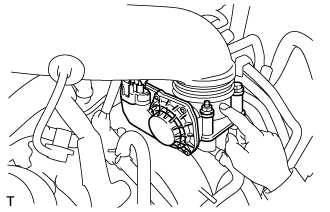
INSTALL FAN & GENERATOR V BELT
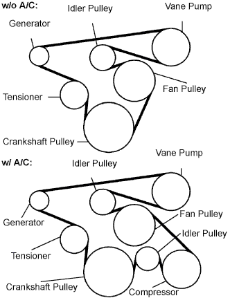
-
Install the drive belt to the pulleys except the drive belt tensioner pulley.
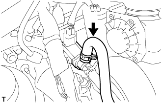
-
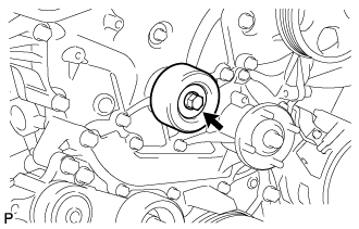
Use the hexagon-shaped part indicated by the arrow in the illustration to move the tensioner pulley downward and then install the drive belt to the tensioner pulley.
Note
-
The backside of the drive belt should face the tensioner pulley.
-
Check that the drive belt is properly set to each pulley.
-
-
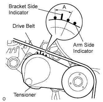
After a new belt has been installed, check that the tensioner indicator mark is within range A shown in the illustration.
-
-
INSTALL ENGINE SERVICE HOLE SUB COVER SUB-ASSEMBLY
-
Install the engine service hole sub cover with the 5 bolts.
- Torque:
- 13 N*m { 133 kgf*cm, 10 ft.*lbf }
-
-
INSTALL FRONT DOOR SCUFF PLATE RH
-
INSTALL FRONT SEAT ASSEMBLY RH (for Hi-back Seat Type)
-
Perform the same procedure as above on the opposite side. Click here
-
-
INSTALL FRONT SEAT ASSEMBLY RH (for Low-back Seat Type)
-
Perform the same procedure as above on the opposite side. Click here
-
-
CONNECT BATTERY NEGATIVE TERMINAL
-
ADD ENGINE OIL
-
ADD ENGINE COOLANT
-
Tighten the radiator drain cock plug by hand.
-
Tighten the cylinder block water drain cock plug.
- Torque:
- 13 N*m { 130 kgf*cm, 9 ft.*lbf }
-
Fill the radiator reservoir assembly with engine coolant to the top of the inlet.
Standard Capacity Item Specified Condition w/o Rear Heater 11.2 liters (11.8 US qts, 9.9 Imp. qts) w/ Rear Heater 13.2 liters (13.9 US qts, 11.6 Imp. qts) Note
Never use water as a substitute for engine coolant.
Tech Tips
TOYOTA vehicles are filled with TOYOTA SLLC at the factory. In order to avoid damage to the engine cooling system and other technical problems, only use TOYOTA SLLC or similar high quality ethylene glycol based non-silicate, non-amine, non-nitrite, non-borate coolant with long-life hybrid organic acid technology (coolant with long-life hybrid organic acid technology is a combination of low phosphates and organic acids).
-
Remove the 2-way that is located near the throttle body assembly.
-
When air is bled and the engine coolant drains out, install the 2-way.
-
Add coolant through the radiator reservoir assembly filler opening until the coolant reaches the B line and install the radiator reservoir cap sub-assembly. [*1]
-
Warm up the engine until the thermostat opens. While the thermostat is open, circulate the coolant for several minutes. [*2]
CAUTION:
-
Wear protective gloves.
-
Be careful as the radiator hoses are hot.
-
Keep your hands away from the radiator fans.
Note
-
Immediately after starting the engine, if the radiator reservoir assembly does not have any engine coolant, perform the following: 1) stop the engine, 2) wait until the engine coolant has cooled down, and 3) add engine coolant.
-
Do not start the engine when there is no engine coolant in the radiator reservoir assembly.
-
Make sure that the needle does not show an abnormally high temperature.
-
If there is not enough engine coolant, the engine may overheat.
Tech Tips
-
Press the No. 2 and No. 3 radiator hoses several times by hand, and then check the level of the engine coolant.
-
The thermostat open timing can be confirmed by pressing the No. 3 radiator hose by hand, and checking when the engine coolant starts to flow inside the hose.
-
-
Stop the engine, and wait until the engine coolant cools down to ambient temperature. [*3]
-
Check the engine coolant level in the radiator reservoir assembly. [*4]
Tech Tips
-
If the engine coolant level is below the LOW line, repeat step *1 through *4.
-
If the engine coolant level is above the FULL line, drain engine coolant until the engine coolant level is between the FULL and LOW lines.
-
-
-
INSPECT FOR FUEL LEAKS
-
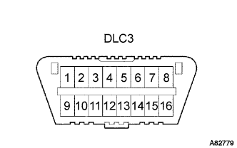
When using the intelligent tester
-
Connect the intelligent tester to the DLC3.
-
Turn the ignition switch to the on position and intelligent tester main switch ON.
Note
Do not start the engine.
-
Select the Active Test mode on the intelligent tester.
Tech Tips
Please refer to the intelligent tester operator's manual for further details.
-
-
When not using the intelligent tester.
-
Disconnect the fuel pump connector.
-
Using a service wire, connect terminals FP and +B of the relay block.
Note
Pay attention to the terminal connecting position to avoid a malfunction.
-
Turn the ignition switch to the ON position, and check that the fuel pump operates.
Note
Do not start the engine.
-
-
Check that there are no fuel leaks anywhere on the fuel system after doing maintenance.
-
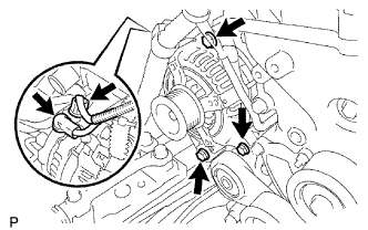
Check that the pulsation damper screw rises up when the fuel pump operates.
If operation is not as specified, check the following parts:
-
Fusible link
-
Fuel pump
-
Wiring connections
-
ECM
-
Fuses
-
-
Turn the ignition switch off.
-
Disconnect the intelligent tester from the DLC3.
-
-
INSPECT ENGINE OIL LEAKS
-
CHECK FOR ENGINE COOLANT LEAKS
CAUTION:
Do not remove the radiator cap while the engine and radiator are still hot. Pressurized, hot engine coolant and steam may be released and cause serious burns.
-
Fill the radiator with coolant and attach a radiator cap tester to the radiator.
-
Warm up the engine.
-
Using a radiator cap tester, increase the pressure inside the radiator to 137 kPa (1.4 kgf/cm2, 19.9 psi), and check that the pressure does not drop.
Tech Tips
If the pressure drops, check the hoses, radiator or water pump for leaks. If no external leaks are found, check the heater core, cylinder block and cylinder head.
-
-
INSTALL ENGINE SIDE UNDER COVER LH (w/ Engine Side Under Cover LH)
-
INSTALL ENGINE SIDE UNDER COVER RH (w/ Engine Side Under Cover RH)
-
INSTALL ENGINE UNDER COVER NO.2 (w/ Engine Under Cover No.2)
-
INSTALL ENGINE UNDER COVER NO.1 (w/ Engine Under Cover No.1)
-
CHECK IDLE SPEED AND IGNITION TIMING
-
CHECK FUNCTION OF THROTTLE BODY
-
Check the throttle control motor operating sounds.
-
Turn the ignition switch to the ON position.
-
When pressing the accelerator pedal, listen to the running sounds of the motor. Make sure no friction noise comes from the motor.
If friction noise exists, replace the throttle body.
-
-
Check the throttle position sensor.
-
Connect the intelligent tester to the DLC3.
-
Turn the ignition switch to the ON position.
-
Turn the intelligent tester main switch on.
-
Enter the following menus: Power train / Engine / Data List / Throttle Sensor Position and Throttle Position Sensor Position #2.
-
Depress the accelerator pedal. When the throttle valve is fully opened, check that the value of the "Throttle Sensor Position" is within the specification.
Standard throttle valve opening percentage 60% or more Note
When checking the standard throttle valve opening percentage, the shift lever should be in the N position.
Tech Tips
If the percentage is less than 60%, replace the throttle body.
-
-
-
PERFORM INITIALIZATION