ENGINE STOP AND START ECU REMOVAL
PROCEDURE
PRECAUTION
Note:After turning the ignition switch off, waiting time may be required before disconnecting the cable from the negative (-) battery terminal. Therefore, make sure to read the disconnecting the cable from the negative (-) battery terminal notices before proceeding with work.
READ NUMBER OF STARTER OPERATIONS
DISCONNECT CABLE FROM NEGATIVE BATTERY TERMINAL
Note:When disconnecting the cable, some systems need to be initialized after the cable is reconnected.
REMOVE MAIN BODY ECU (MULTIPLEX NETWORK BODY ECU)
SEPARATE NO. 2 CONNECTOR HOLDER
-
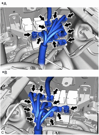
*A
for LHD
*B
for RHD
Disconnect the 10 No. 2 connector holder connectors.
-
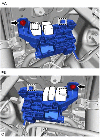
*A
for LHD
*B
for RHD
Remove the bolt from the No. 2 connector holder.
Disengage the 2 clamps to separate the No. 2 connector holder.
-
REMOVE ENGINE STOP AND START ECU
-
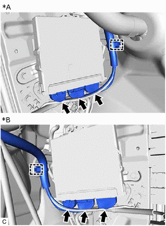
*A
for LHD
*B
for RHD
Disconnect the 3 engine stop and start ECU connectors and disengage the clamp.
-
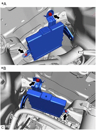
*A
for LHD
*B
for RHD
Remove the 2 bolts and engine stop and start ECU.
-