ELECTRONICALLY CONTROLLED BRAKE SYSTEM Brake Control Warning Light Remains ON
DESCRIPTION
The skid control ECU is connected to the combination meter sub-assembly via CAN communication.
If the skid control ECU stores a DTC, the brake warning light / yellow (minor malfunction) comes on in the combination meter sub-assembly.
WIRING DIAGRAM
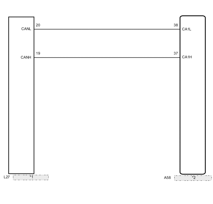
| *1 | Combination Meter Sub-assembly |
| *2 | Brake Booster with Master Cylinder |
CAUTION / NOTICE / HINT
Note
When replacing the brake booster with master cylinder (skid control ECU), perform initialization and calibration of the linear solenoid valve Click here.
PROCEDURE
-
CHECK CAN COMMUNICATION SYSTEM
-
Check if a CAN communication system DTC is output (See page for with Central Gateway ECU or Click here for without Central Gateway ECU).
Result Result Proceed to DTC is not output A DTC is output (w/ Central Gateway ECU) B DTC is output (w/o Central Gateway ECU) C
B 
INSPECT CAN COMMUNICATION SYSTEM Click here
C
INSPECT CAN COMMUNICATION SYSTEM Click here
A 
-
-
CHECK IF SKID CONTROL ECU CONNECTOR IS SECURELY CONNECTED
-
Check if the skid control ECU connector is securely connected.
OK The connector is securely connected.
NG
CONNECT CONNECTOR TO ECU CORRECTLY
OK
-
-
CHECK AUXILIARY BATTERY
-
Check the auxiliary battery voltage.
Standard Voltage 11 to 14 V
NG
CHARGE OR REPLACE AUXILIARY BATTERY
OK
-
-
INSPECT COMBINATION METER SUB-ASSEMBLY
-
Perform the Active Test of the combination meter sub-assembly (meter CPU) using the GTS Click here.
-
Check the combination meter sub-assembly.
OK The brake warning light / yellow (minor malfunction) turns on or off in accordance with the GTS operation. Result Result Proceed to OK (for LHD) A OK (for RHD) B NG (w/ Multi-information Display) C NG (w/o Multi-information Display) D Tech Tips
If troubleshooting has been carried out according to Problem Symptoms Table refer back to the table and proceed to the next step before replacing the part Click here.
A
REPLACE BRAKE BOOSTER WITH MASTER CYLINDER Click here
B
REPLACE BRAKE BOOSTER WITH MASTER CYLINDER Click here
C
REPLACE COMBINATION METER SUB-ASSEMBLY Click here
D
REPLACE METER CIRCUIT PLATE Click here
-