THEFT DETERRENT SYSTEM Ignition Switch Circuit
DESCRIPTION
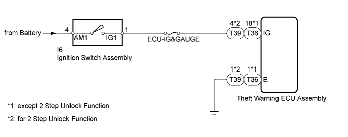
When the ignition switch assembly is turned ON, voltage is applied to terminal IG of the theft warning ECU assembly.
WIRING DIAGRAM
INSPECTION PROCEDURE
Note
Inspect the fuses for circuits related to this system before performing the following inspection procedure.
PROCEDURE
-
INSPECT IGNITION SWITCH ASSEMBLY
-
Remove the ignition switch assembly.
-
for 1KD-FTV: Click here
-
for 2KD-FTV: Click here
-
for 1TR-FE: Click here
-
for 2TR-FE: Click here
-
for 1GR-FE: Click here
-
-
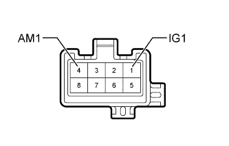
Measure the resistance according to the value(s) in the table below.
Standard Resistance Tester Connection Switch Condition Specified Condition 1 (IG1) - 4 (AM1) Off, ACC 10 kΩ or higher 1 (IG1) - 4 (AM1) ON, Start Below 1 Ω Tech Tips
If replacing the ignition switch assembly, refer to the procedures below.
-
for 1KD-FTV: Click here
-
for 2KD-FTV: Click here
-
for 1TR-FE: Click here
-
for 2TR-FE: Click here
-
for 1GR-FE: Click here
-
NG 
REPLACE IGNITION SWITCH ASSEMBLY
OK 
-
-
CHECK HARNESS AND CONNECTOR (THEFT WARNING ECU - BATTERY AND BODY GROUND)
-
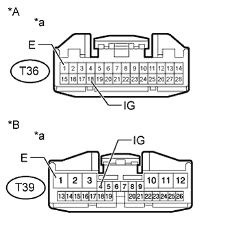
Text in Illustration *A except 2 Step Unlock Function *B for 2 Step Unlock Function *a Front view of wire harness connector
(to Theft Warning ECU Assembly)
Disconnect the T36*1 or T39*2 theft warning ECU assembly connector.
-
*1: except 2 Step Unlock Function
-
*2: for 2 Step Unlock Function
-
-
Measure the resistance according to the value(s) in the table below.
Standard Resistance except 2 Step Unlock Function Tester Connection Condition Specified Condition T36-1 (E) - Body ground Always Below 1 Ω for 2 Step Unlock Function Tester Connection Condition Specified Condition T39-1 (E) - Body ground Always Below 1 Ω -
Measure the voltage according to the value(s) in the table below.
Standard Voltage except 2 Step Unlock Function Tester Connection Switch Condition Specified Condition T36-18 (IG) - Body ground Ignition switch off Below 1 V T36-18 (IG) - Body ground Ignition switch ON 11 to 14 V for 2 Step Unlock Function Tester Connection Switch Condition Specified Condition T39-4 (IG) - Body ground Ignition switch off Below 1 V T39-4 (IG) - Body ground Ignition switch ON 11 to 14 V
NG
REPAIR OR REPLACE HARNESS OR CONNECTOR
OK 
PROCEED TO NEXT CIRCUIT INSPECTION SHOWN IN PROBLEM SYMPTOMS TABLE Click here
-