DYNAMIC RADAR CRUISE CONTROL SYSTEM ECU Power Source Circuit
| DTC Code | DTC Name |
|---|---|
| ECU Power Source Circuit |
DESCRIPTION
This circuit provides power to operate the driving support ECU.
WIRING DIAGRAM

CAUTION / NOTICE / HINT
Inspect the fuses for circuits related to this system before performing the following inspection procedure.
PROCEDURE
CHECK HARNESS AND CONNECTOR (DRIVING SUPPORT ECU - BATTERY AND BODY GROUND)
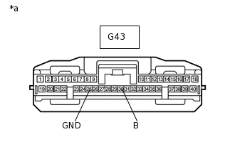
*a
Front view of wire harness connector(to Driving Support ECU)
Note:A DTC is stored when the following inspection is performed. Be sure to clear the DTC after performing this inspection.
Disconnect the G43 driving support ECU connector.
Measure the voltage according to the value(s) in the table below.
Standard Voltage
Tester Connection
Switch Condition
Specified Condition
G43-30 (B) - Body ground
Engine switch on (IG)
11 to 14 V
G43-30 (B) - Body ground
Engine switch off
Below 1 V
Measure the resistance according to the value(s) in the table below.
Standard Resistance
Tester Connection
Condition
Specified Condition
G43-25 (GND) - Body ground
Always
Below 1 Ω
Result
Result
OK
NG
NG REPAIR OR REPLACE HARNESS OR CONNECTOR