VEHICLE STABILITY CONTROL SYSTEM, Diagnostic DTC:C1256
| DTC Code | DTC Name |
|---|---|
| C1256 | Accumulator Low Pressure |
DESCRIPTION
Refer to DTC C1254 (Click here).
DTC No. |
Detection Item |
DTC Detection Condition |
Trouble Area |
|---|---|---|---|
C1256 |
Accumulator Low Pressure |
The fluid pressure inside the accumulator is below the standard value. |
|
CAUTION / NOTICE / HINT
When replacing the master cylinder solenoid, perform calibration (Click here).
When DTC C1251, C1253, or C1254 is output together with DTC C1256 inspect and repair the trouble area indicated by DTC C1251, C1253, or C1254 first.
PROCEDURE
RECONFIRM DTC
Clear the DTCs.
Chassis > ABS/VSC/TRC > Clear DTCs
Turn the engine switch off.
Depress the brake pedal 20 times or more.
Turn the engine switch on (IG).
Wait for 99 seconds.
Check if the same DTC is output.
Chassis > ABS/VSC/TRC > Trouble Codes
Result
Result
Proceed to
DTC is output
A
DTC is not output
B
Tip:Excessive brake pedal operation results in abnormal accumulator pressure consumption. This is normal.
INSPECT HYDRAULIC BRAKE BOOSTER ASSEMBLY FUNCTION
Inspect brake booster pump power supply system function.
Turn the engine switch off.
Depress the brake pedal 20 times or more to release the pressure in the accumulator.
Tip:When the pressure is released, the brake pedal stroke becomes longer.
Check that the brake fluid level is at the MAX level.
Chock the 4 wheels and release the parking brake.
Turn the engine switch on (IG) and measure the brake booster pump operating time (the time from when the brake booster pump starts operating until it stops).
OK
20 to 80 seconds
Start the engine after the brake boost pump stops.
Check that the ABS warning light and slip indicator light are not illuminated.
Turn off the engine, and then turn the engine switch on (IG).
Check that the brake boost pump operates and then stops when the brake pedal is depressed 4 or 5 times.
Depress the brake pedal 4 or 5 times and measure the brake booster pump operating time (the time from when the brake booster pump starts operating until it stops).
OK
2 to 11 seconds
Check that the brake warning light illuminates and the buzzer sounds when the brake pedal is fully depressed continuously 15 to 20 times.
Note:Wait 120 seconds or more after turning the engine switch on (IG) before performing this inspection.
Check brake booster operation.
Turn the engine switch off.
Depress the brake pedal 20 times or more to release the pressure in the accumulator.
Tip:When the pressure is released, the brake pedal stroke becomes longer.
Depress the brake pedal, start the engine, and check the change in the brake pedal height.
OK
The brake pedal moves slightly inward.
Inspect brake master cylinder fluid pressure change.
Result
Result
OK
NG
NG INSPECT BRAKE BOOSTER PUMP ASSEMBLYClick here
READ VALUE USING INTELLIGENT TESTER (ACCUMULATOR SENSOR)
Connect the intelligent tester to the DLC3.
Turn the engine switch on (IG).
Turn the intelligent tester on.
Enter the following menus: Chassis / ABS/VSC/TRC / Data List.
Chassis > ABS/VSC/TRC > Data List
Tester Display
Accumulator Sensor
Chassis > ABS/VSC/TRC > Data List
Tester Display
Measurement Item
Range
Normal Condition
Diagnostic Note
Accumulator Sensor
Accumulator pressure sensor reading
Min.: 0.00 V, Max.: 5.00 V
3.58 to 5 V
If the value is constant regardless of the pump operation, an accumulator pressure sensor malfunction is suspected.
Check that the accumulator output value is normal.
OK
Accumulator pressure sensor value is normal.
Result
Result
OK
NG
RECONFIRM DTC
Clear the DTCs.
Chassis > ABS/VSC/TRC > Clear DTCs
Check if the same DTC is output.
Chassis > ABS/VSC/TRC > Trouble Codes
Result
Result
Proceed to
DTC is not output
A
DTC is output
B
INSPECT BRAKE BOOSTER PUMP ASSEMBLY
Remove the hydraulic brake booster assembly.
Using a screwdriver, remove the 2 screws and pull out the wire harness from the master cylinder solenoid.
-
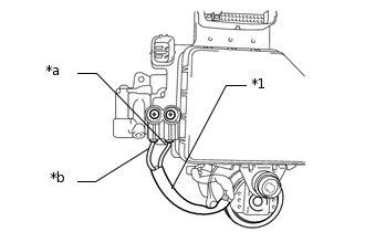
*1
Pump motor wire harness
*a
Red wire
*b
Black wire
Measure the resistance according to the value(s) in the table below.
Standard Resistance
Tester Connection
Condition
Specified Condition
Red wire terminal - Black wire terminal
Always
Below 2 Ω
Install the pump motor wire harness to the master cylinder solenoid with the 2 screws.
2.9 N*m
30 kgf*cm
26 in.*lbf
Result
Result
OK
NG