PRE-CRASH SAFETY SYSTEM Reverse Signal Circuit
| DTC Code | DTC Name |
|---|---|
| Reverse Signal Circuit |
DESCRIPTION
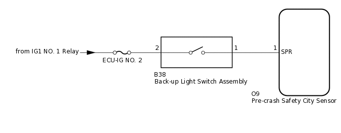
While the vehicle is driven with the shift lever in R, the buck-up light switch assembly sends a reverse signal to terminal (SPR) of the pre-crash safety city sensor. The pre-crash safety city sensor cancels pre-crash safety system when terminal (SPR) receives the reverse signal.
WIRING DIAGRAM
CAUTION / NOTICE / HINT
Inspect the fuses for circuits related to this system before performing the following procedure.
When replacing the pre-crash safety city sensor, replace it with a new one and be sure to initialize the settings. If a pre-crash safety city sensor which was installed to another vehicle is used, the information stored in the pre-crash safety city sensor will not match the information from the vehicle and, as a result, a DTC may be stored.
If the pre-crash safety city sensor has been replaced, or the windshield glass has been replaced or removed/installed, be sure to perform Recognition Camera/Target Position Memory and Recognition Camera Axis Adjust.
PROCEDURE
CHECK PRE-CRASH SAFETY CITY SENSOR
Check pre-crash safety city sensor.
Note:DTCs may be output when connectors are disconnected during inspection. Therefore, make sure to clear the DTCs using the GTS once the inspection has been completed.
-
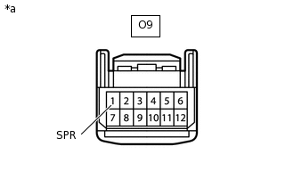
*a
Front view of wire harness connector
(to Pre-crash Safety City Sensor)
Disconnect the pre-crash safety city sensor connector.
Measure the voltage according to the value(s) in the table below.
Standard Voltage
Tester Connection
Condition
Specified Condition
O9-1 (SPR) - Body ground
Ignition switch ON, shift lever in R
11 to 14 V
O9-1 (SPR) - Body ground
Ignition switch ON, shift lever not in R
Below 1 V
-
Result
Proceed to
OK
NG
CHECK HARNESS AND CONNECTOR (BACK-UP LIGHT SWITCH ASSEMBLY - PRE-CRASH SAFETY CITY SENSOR)
Disconnect the B38 back-up light switch assembly connector.
Disconnect the O9 pre-crash safety city sensor connector.
Measure the resistance according to the value(s) in the table below.
Standard Resistance
Tester Connection
Condition
Specified Condition
B38-1 - O9-1 (SPR)
Always
Below 1 Ω
B38-1 - Body ground
Always
10 kΩ or higher
O9-1 (SPR) - Body ground
Always
10 kΩ or higher
Result
Proceed to
OK
NG
NG REPAIR OR REPLACE HARNESS OR CONNECTOR
CHECK HARNESS AND CONNECTOR (BACK-UP LIGHT SWITCH ASSEMBLY POWER SORCE)
Disconnect the B38 back-up light switch assembly connector.
Measure the voltage according to the value(s) in the table below.
Standard Voltage
Tester Connection
Condition
Specified Condition
B38-2 - Body ground
Ignition switch ON
11 to 14 V
Result
Proceed to
OK
NG
NG REPAIR OR REPLACE HARNESS OR CONNECTOR
INSPECT BACK-UP LIGHT SWITCH ASSEMBLY
Inspect the back-up light switch assembly.
for EC6A:Click here
for EC60:Click here
for EC61:Click here
for EC69:Click here
Result
Proceed to
OK
NG
NG REPLACE BACK-UP LIGHT SWITCH ASSEMBLY