ENGINE IMMOBILISER SYSTEM Immobiliser System does not Operate Properly
DESCRIPTION
The engine immobiliser system compares the ID code that is registered in the certification ECU (smart key ECU assembly) with the ID code of the transponder chip that is embedded in the electrical key transmitter sub-assembly.
WIRING DIAGRAM
CAUTION / NOTICE / HINT
CAUTION:
-
The engine immobiliser system uses the LIN communication system. Inspect the communication function by following How to Proceed with Troubleshooting. Troubleshoot the engine immobiliser system after confirming that the communication systems are functioning properly Click here.
-
Before replacing the hybrid vehicle control ECU or ID code box (immobiliser code ECU), refer to Service Bulletin..
-
After repair, confirm that no DTCs are output by performing "DTC Output Confirmation Operation".
Tech Tips
If an engine immobiliser system or SFI system DTC is output, first perform troubleshooting for the engine immobiliser system or SFI system DTC.
PROCEDURE
-
CHECK FOR DTC
-
Check for DTCs Click here.
Result Result Proceed to DTCs are not output A DTCs are output B
B 
GO TO DIAGNOSTIC TROUBLE CODE CHART Click here
A 
-
-
CHECK WHETHER HYBRID CONTROL SYSTEM STARTS
-
Check that the hybrid control system starts 5 seconds after the power switch turned on (IG).
OK Hybrid control system starts normally. Result Result Proceed to NG A OK B
B
USE SIMULATION METHOD TO CHECK Click here
A
-
-
CHECK HYBRID VEHICLE CONTROL ECU (TERMINAL IMI AND IMO)
-
Using an oscilloscope, check the waveform.
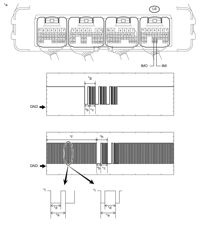
Text in Illustration *a Component with harness connected
(Hybrid Vehicle Control ECU)
*b Approximately 160 ms *c Approximately 270 ms *d Approximately 40 ms *e Approximately 60 ms *f Waveform 1 *g Waveform 2 *h Waveform 3 *i Waveform 1 (detail) - - Measurement Condition Tester Connection Condition Tool Setting Specified Condition L6-23 (IMO) - Body ground Within 3 seconds of hybrid control system start or within 3 seconds of power switch turned on (IG) after auxiliary battery cable disconnected and reconnected 2 V/DIV., 500 ms./DIV. Pulse generation
(See waveform 2)
L6-22 (IMI) - Body ground Within 3 seconds of hybrid control system start or within 3 seconds of power switch turned on (IG) after auxiliary battery cable disconnected and reconnected 2 V/DIV., 500 ms./DIV. Pulse generation
(See waveform 1 and 3)
Result Result Proceed to Normal waveform A Waveform 1 not output, or has abnormal wavelength or shape B Waveform 2 not output, or has abnormal wavelength or shape C Waveform 3 not output, or has abnormal wavelength or shape D
B 
CHECK HARNESS AND CONNECTOR (ID CODE BOX (IMMOBILISER CODE ECU) - HYBRID VEHICLE CONTROL ECU) Click here
C
REPLACE HYBRID VEHICLE CONTROL ECU Click here
D
REPLACE ID CODE BOX (IMMOBILISER CODE ECU) Click here
A
-
-
REGISTER ECU COMMUNICATION ID
-
Register the ECU communication ID.
Tech Tips
Refer to Service Bulletin.
NEXT
-
-
CHECK WHETHER HYBRID CONTROL SYSTEM STARTS
-
Check that the hybrid control system starts.
OK Hybrid control system starts normally.
OK
END (COMMUNICATION ID REGISTRATION WAS DEFECTIVE)
NG
REPLACE ID CODE BOX (IMMOBILISER CODE ECU) Click here
-
-
CHECK HARNESS AND CONNECTOR (ID CODE BOX (IMMOBILISER CODE ECU) - HYBRID VEHICLE CONTROL ECU)
-
Disconnect the L191 ID code box (immobiliser code ECU) connector.
-
Disconnect the L6 hybrid control system connector.
-
Measure the resistance according to the value(s) in the table below.
Standard Resistance Tester Connection Condition Specified Condition L191-3 (EFII) - L6-23 (IMO) Always Below 1 Ω L191-3 (EFII) or L6-23 (IMO) - Body ground Always 10 kΩ or higher L191-4 (EFIO) - L6-22 (IMI) Always Below 1 Ω L191-4 (EFIO) or L6-22 (IMI) - Body ground Always 10 kΩ or higher
NG
REPAIR OR REPLACE HARNESS OR CONNECTOR
OK
-
-
REPLACE ID CODE BOX (IMMOBILISER CODE ECU)
-
Replace the ID code box (immobiliser code ECU) with a new one.
Tech Tips
Refer to Service Bulletin.
NEXT
-
-
REGISTER RECOGNITION CODE
-
Register the recognition codes in the ECUs.
Tech Tips
Refer to Service Bulletin.
NEXT
-
-
REGISTER ECU COMMUNICATION ID
-
Register the ECU communication ID.
Tech Tips
Refer to Service Bulletin.
NEXT
-
-
CHECK WHETHER HYBRID CONTROL SYSTEM STARTS
-
Check that the hybrid control system starts.
OK Hybrid control system starts normally.
OK
END (ID CODE BOX (IMMOBILISER CODE ECU) WAS DEFECTIVE)
NG
GO TO HYBRID CONTROL SYSTEM Click here
-