KNOCK SENSOR INSTALLATION
Tech Tips
Perform "Inspection After Repairs" after replacing the knock control sensor Click here.
-
INSTALL KNOCK CONTROL SENSOR
Tech Tips
Perform "Inspection After Repairs" after replacing the knock control sensor Click here.
-
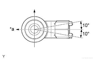
Text in Illustration *a Front Install the knock control sensor with the bolt as shown in the illustration.
- Torque:
- 20 N*m { 204 kgf*cm, 15 ft.*lbf }
-
Connect the knock control sensor connector.
-
-
INSTALL INTAKE MANIFOLD
-
Install a new gasket onto the intake manifold.
-
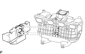
Text in Illustration *1 Intake Manifold Insulator *a Line Install the intake manifold insulator to the intake manifold.
Tech Tips
Insert the protrusions of the intake manifold insulator into the grille of the intake manifold.
Note
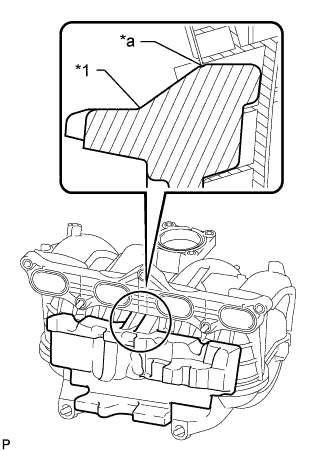
Insert the intake manifold insulator until the position of the line as shown in the illustration.
-
Install the intake manifold with the 5 bolts and 2 nuts.
- Torque:
- 25 N*m { 255 kgf*cm, 18 ft.*lbf }
-
Install the bolt and wire harness bracket to the intake manifold.
- Torque:
- 8.5 N*m { 87 kgf*cm, 75 in.*lbf }
-
Connect the vacuum hose to the intake manifold, and slide the clamp to secure the hose.
-
Connect the No. 3 PCV hose to the intake manifold, and slide the clamp to secure the hose.
-
Attach the 2 wire harness clamps to the wire harness bracket.
-
Connect the purge line hose to the vacuum switching valve, and slide the clamp to secure the hose.
-
Connect the vacuum switching valve connector.
-
-
INSTALL FUEL INJECTOR ASSEMBLY
-
INSTALL THROTTLE BODY ASSEMBLY
-
ADD ENGINE COOLANT
-
Tighten the radiator drain cock plug by hand.
-
Tighten the cylinder block water drain cock plug.
- Torque:
- 13 N*m { 130 kgf*cm, 9 ft.*lbf }
-
Fill the radiator reservoir assembly with engine coolant to the top of the inlet.
Standard Capacity 11.2 liters (11.8 US qts, 9.9 Imp. qts) Note
Never use water as a substitute for engine coolant.
Tech Tips
TOYOTA vehicles are filled with TOYOTA SLLC at the factory. In order to avoid damage to the engine cooling system and other technical problems, only use TOYOTA SLLC or similar high quality ethylene glycol based non-silicate, non-amine, non-nitrite, non-borate coolant with long-life hybrid organic acid technology (coolant with long-life hybrid organic acid technology is a combination of low phosphates and organic acids).
-
Remove the 2-way that is located near the throttle body assembly.
-
When air is bleed and the engine coolant drains out, install the 2-way.
-
Add coolant through the radiator reservoir assembly filler opening until the coolant reaches the B line and install the radiator reservoir cap sub-assembly. [*1]
-
Warm up the engine until the thermostat opens. While the thermostat is open, circulate the coolant for several minutes. [*2]
CAUTION:
-
Wear protective gloves.
-
Be careful as the radiator hoses are hot.
-
Keep your hands away from the radiator fans.
Note
-
Immediately after starting the engine, if the radiator reservoir assembly does not have any engine coolant, perform the following: 1) stop the engine, 2) wait until the engine coolant has cooled down, and 3) add engine coolant.
-
Do not start the engine when there is no engine coolant in the radiator reservoir assembly.
-
Make sure that the needle does not show an abnormally high temperature.
-
If there is not enough engine coolant, the engine may overheat.
Tech Tips
-
Press the No. 2 and No. 3 radiator hoses several times by hand, and then check the level of the engine coolant.
-
The thermostat open timing can be confirmed by pressing the No. 3 radiator hose by hand, and checking when the engine coolant starts to flow inside the hose.
-
-
Stop the engine, and wait until the engine coolant cools down to ambient temperature. [*3]
-
Check the engine coolant level in the radiator reservoir assembly. [*4]
Tech Tips
-
If the engine coolant level is below the LOW line, repeat steps *1 through *4.
-
If the engine coolant level is above the FULL line, drain engine coolant until the engine coolant level is between the FULL and LOW line.
-
-
-
CONNECT CABLE TO NEGATIVE BATTERY TERMINAL
Note
When disconnecting the cable, some systems need to be initialized after the cable is reconnected Click here.
-
INSPECT FOR COOLANT LEAK
CAUTION:
Do not remove the radiator reservoir cap sub-assembly while the engine and radiator are still hot. Pressurized, hot engine coolant and steam may be released and cause serious burns.
-
Remove the radiator reservoir cap sub-assembly.
-
Fill the radiator reservoir assembly with engine coolant, and then attach a radiator cap tester.
-
Warm up the engine.
-
Using the radiator cap tester, increase the pressure inside the radiator to 137 kPa (1.4 kgf/cm2, 20 psi), and then check that the pressure does not drop.
If the pressure drops, check the hoses, radiator assembly and engine water pump assembly for leakage.
If there are no signs or traces of external engine coolant leakage, check the heater core, cylinder block assembly and cylinder head sub-assembly.
-
Install the radiator reservoir cap sub-assembly.
-