AIR CONDITIONING SYSTEM
-
SYSTEM CONTROL
-
The air conditioning system uses the following controls:
Control Outline Neural Network Control This control is capable of effecting complex control by artificially simulating the information processing method of the nervous system of living organisms in order to establish a complex input/output relationship that is similar to that of a human brain. Micro Dust and Pollen Filter Mode Control Activated by the micro dust and pollen filter mode switch operation. Switches the air outlet to the FACE mode. Sends air which has passed through the clean air filter to the area around the upper part of the bodies of the driver and front passenger. This air is filtered by the clean air filter in order to remove pollen. Outlet Air Temperature Control Based on the temperature set at the temperature control switch, the neural network control calculates the outlet air temperature based on the input signals from various sensors. The temperature settings for the driver and front passenger are controlled independently in order to provide a separate vehicle interior temperature for the right and left sides of the vehicle. As a result, air conditioning control that accommodates occupant preferences has been achieved. Blower Control Controls the blower motor in accordance with the airflow volume that has been calculated by the neural network control based on the input signals from various sensors. Air Outlet Control Automatically switches the air outlets in accordance with the outlet mode that has been calculated by the neural network control based on the input signals from various sensors. Compressor Control The air conditioning amplifier assembly calculates the target speed of the compressor based on the target evaporator temperature (which is calculated by the room temperature sensor, ambient temperature sensor and solar sensor) and the actual evaporator temperature that is detected by the evaporator temperature sensor in order to control the compressor speed. Turns the air conditioning on automatically when the AUTO button is pressed when the blower is on and the air conditioning is OFF. Decreases the compressor speed in order to ensure quietness when the vehicle is stopped or the engine is off. PTC Heater Control When the power switch is turned on (IG) and the blower motor is turned on, the air conditioning amplifier assembly turns on the PTC heater (quick heater assembly) if the following conditions are met.
-
Engine coolant temperature is below the specified temperature.
-
Ambient temperature is below the specified temperature
-
Tentative air mix damper opening angle is above the specified value (MAX HOT).
Windshield Deicer Control*1 Switches the windshield deicer on for approx. 15 minutes when the windshield deicer switch is pressed. Turns on when the hybrid system is started while the outside temperature is low, and turns off after approx. 15 minutes automatically. Heated Windshield Defroster Control*2 The heated windshield defroster system is activated when the power switch is turned on (IG) and the heated windshield defroster switch is pushed. The air conditioning amplifier assembly keeps the heated windshield defroster system on for approximately 4 minutes if the outside temperature is at the predetermined level or lower. Rear Window Defogger Control Switches the rear window defogger on for 15 minutes when the rear window defogger switch is pressed. Switches the rear window defogger off if the switch is pressed while it is operating. ECO Drive Mode Control When set to ECO drive mode, the air conditioning amplifier assembly decreases the blower speed. Blower Customization Control*3 The air volume can be adjusted to 3 levels using the FAST SOFT switch: MEDIUM-SOFT (small air volume)-FAST (large air volume) Electric Power Control
-
When the vehicle voltage is below the specified level, the air conditioning amplifier assembly saves the power source of some systems in accordance with the voltage signal from the hybrid vehicle control ECU
-
When the electric power control is operating, the combination meter assembly warns the driver by indicating a message on the multi-information display.
-
*1: Models with windshield deicer system
-
*2: Models with heated windshield defroster
-
*3: Models with blower customization control
-
-
Neural Network Control
-
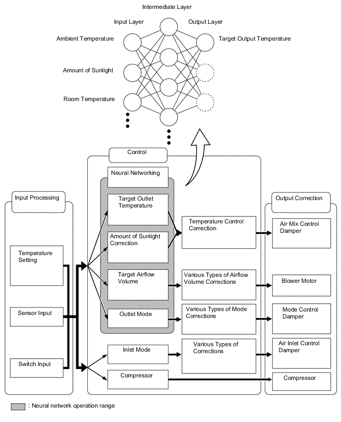
In the previous automatic air conditioning system, the air conditioning amplifier assembly determined the required outlet air temperature and blower air volume in accordance with a calculation formula that had been obtained based on information received from the sensors. However, because the sensors of a person are rather complex, a given temperature is sensed differently, depending on the environment in which the person is situated. For example, a given amount of solar radiation can feel comfortably warm in a cold climate, but extremely uncomfortable in a hot climate. Therefore, as a technique for effecting a high level of control, a neural network is used in the automatic air conditioning system. With this technique, the data that has been collected under varying environmental conditions is stored in the air conditioning amplifier assembly, which effects control to provide enhanced air conditioning comfort.
-
The neural network control consists of neurons in an input layer an intermediate layer, and an output layer. The input layer neurons process the input data of the ambient temperature, the amount of sunlight and the room temperature based on the outputs of the switches and sensors, and output them to the intermediate layer neurons. Based on this data, the intermediate layer neurons adjust the strength of the links among the neurons. The sum of this data is then calculated by the output layer neurons in the form of the required outlet temperature, solar correction, target airflow volume and outlet mode control volume. Accordingly, the air conditioning amplifier assembly controls the servo motors and blower with fan motor sub-assembly in accordance with the control volumes that have been calculated by the neural network control.
-
-
ECO Drive Mode Control
-
During ECO drive mode, the air conditioning amplifier assembly restricts the air conditioning system performance under specified conditions, thus improving fuel economy.
-
The ECO drive mode control is activated when the Eco mode switch is pushed, and then restricts the air conditioning system performance as described below:
Control Outline Inside/Outside Air Switch Control Automatically switches the air inlet port to the internal air circulation mode when the outside air temperature is equal to or higher than a predetermined temperature and reduces the power consumption. Blower Level Control Sets the blower level in AUTO mode lower than normal, and suppresses the power consumption.
-
-
Quick Heater Control
-
The on/off function of the quick heater assembly is controlled by the air conditioning amplifier assembly in accordance with the engine coolant temperature, engine speed, air mix setting and electrical load (alternator power ratio).
-
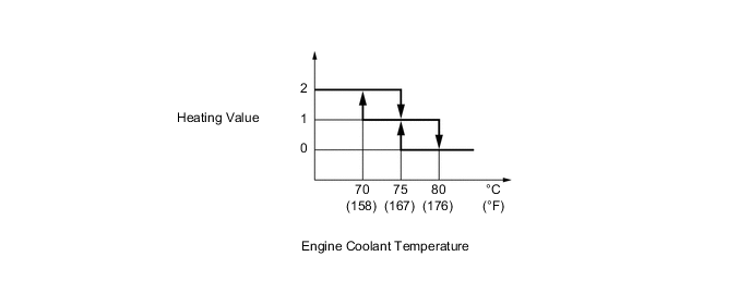
For example, the heating value of the operating quick heater assembly varies depending on the engine coolant temperature, as in the graph below:
Figure 1. Heating Value of Operating Quick Heater Assembly
-
-
Micro Dust and Pollen Filter Mode Control
-
When the micro dust and pollen filter mode switch is pressed, the micro dust and pollen filter mode control is activated. Then, the air outlet is switched to the FACE mode and recirculated pollen-free air flows in the area around the upper part of the bodies of the driver and front passenger.
-
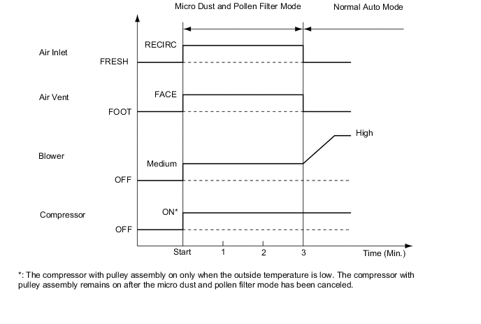
When the micro dust and pollen filter mode switch signal is input to the air conditioning amplifier assembly, the air conditioning amplifier assembly controls the compressor with pulley assembly, No. 1 damper servo sub-assembly, No. 3 air conditioning radiator damper servo sub-assembly and blower with fan motor sub-assembly as shown in the timing chart below.
-
This control usually operates for approximately 3 minutes. However, when the ambient temperature is low [5 °C (41 °F) maximum], it will operate for approximately 1 minute.
-
After this control stops operating, the air conditioning amplifier assembly automatically returns to the mode it was in just before the pollen removal mode switch was pressed.
-
-
-