FUEL INJECTION PUMP INSTALLATION
-
INSTALL INJECTION PUMP ASSEMBLY
-
Install the injection pump to the timing gear case, and temporarily tighten the 2 nuts.
-
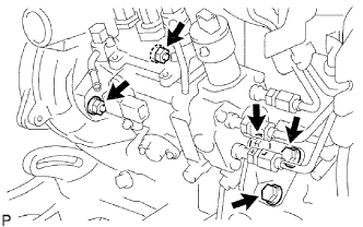
Install the injection pump stay to the injection pump rear end, and temporarily tighten the 3 bolts.
-
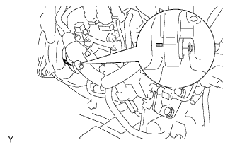
Rotate the pump body to align the marking of the pump flange and timing gear case.
-
Tighten the 2 nuts to install the injection pump.
- Torque:
- 21 N*m { 210 kgf*cm, 15 ft.*lbf }
-
Tighten the 3 bolts to install the injection pump stay.
- Torque:
- 26 N*m { 265 kgf*cm, 19 ft.*lbf, for injection pump stay to cylinder block }
- Torque:
- 26 N*m { 265 kgf*cm, 19 ft.*lbf, for injection pump stay to injection pump }
-
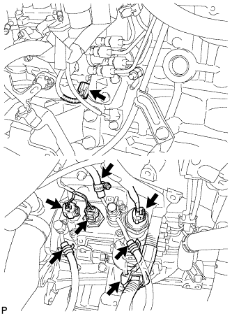
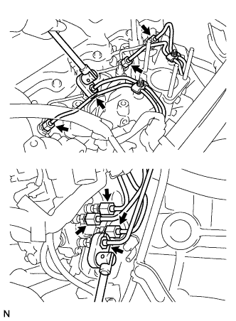
Connect the 3 fuel hoses.
-
Connect the engine speed sensor connector.
-
Connect the spill control valve connector.
-
Connect the correction unit connector.
-
Connect the timing control valve connector.
-
Connect the fuel temperature sensor connector.
-
Connect the engine wire clamp.
-
-
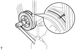
INSTALL INJECTION PUMP DRIVE PULLEY
-
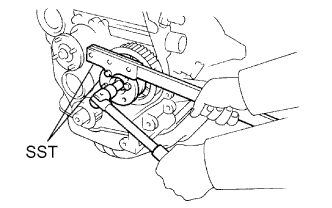
Using SST, install the injection pump drive pulley with the nut.
- SST
- 09213-14010 ( 91651-60865 )
- 09330-00021
- Torque:
- 64 N*m { 650 kgf*cm, 47 ft.*lbf }
-
-
INSTALL INJECTION PIPE SET
-
Connect the 2 lower clamps on the intake manifold.
-
Using a union nut wrench, install the 4 injection pipes.
- Torque:
- 24.5 N*m { 250 kgf*cm, 18 ft.*lbf }
-
Secure the injection pipes with the 2 upper pipe clamps and 2 nuts.
- Torque:
- 5.0 N*m { 51 kgf*cm, 44 in.*lbf }
-
-
INSTALL VENTURI
-
Place a new gasket and the venturi on the intake manifold.
-
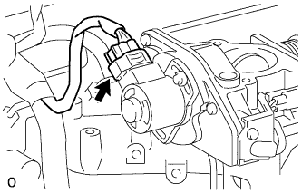
Connect the throttle control motor connector.
-
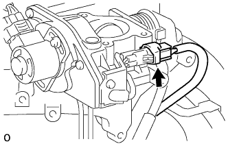
Connect the throttle open switch connector.
-
-
INSTALL INTAKE PIPE ASSEMBLY
-
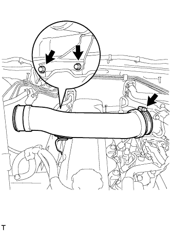
Connect the intake pipe to the intake flange with the clamp.
-
Fix the intake pipe in place with the 2 bolts and clamp.
- Torque:
- 18 N*m { 184 kgf*cm, 13 ft.*lbf, for bolt }
- 6.0 N*m { 61 kgf*cm, 53 in.*lbf, for clamp }
-
-
INSTALL AIR CLEANER HOSE
-
Connect the air cleaner hose to the air cleaner and intake pipe with the 2 clamps.
-
Fix the intake pipe in place with the 2 clamps.
- Torque:
- 5.0 N*m { 51 kgf*cm, 44 in.*lbf }
-
Connect the IAT sensor connector.
-
Attach the clamp of the IAT sensor harness.
-
-
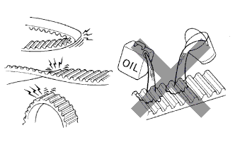
INSPECT TIMING BELT
Note
-
Do not bend, twist or turn the timing belt inside out.
-
Do not allow the timing belt to come into contact with oil, water or steam.
-
If there is premature parting:
-
Check for proper installation.
-
Check the timing cover gasket for damage and proper installation.
-
-
If the belt teeth are cracked or damaged, check if either camshaft is locked.
-
If there is noticeable wear or cracks on the belt face, check if there are nicks on the side of the idler pulley lock and water pump.
-
If there is wear or damage to only one side of the belt, check the belt guide and the alignment of each pulley.
-
If there is noticeable wear on the belt teeth:
-
Check the timing cover for damage.
-
Check that the gasket has been installed correctly.
-
Check for foreign matter on the pulley teeth.
If necessary, replace the timing belt.
-
-
-
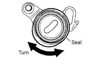
INSPECT TIMING BELT IDLER
-
Visually check the seal portion of the No. 1 timing belt idler for oil leakage. If leakage is found, replace the No. 1 timing belt idler.
-
Check that the No. 1 timing belt idler turns smoothly. If necessary, replace the No. 1 timing belt idler sub-assembly.
-
-
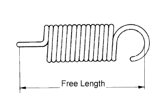
INSPECT IDLER TENSION SPRING
-
Measure the free length of the tension spring.
Standard free length 44.4 to 45.4 mm (1.748 to 1.787 in.) If the free length is not as specified, replace the tension spring.
-
Measure the tension of the tension spring at the specified installed length.
Installed tension 53 to 59 N (5.42 to 5.98 kgf, 11.9 to 13.2 lbf) at 52.1 mm (2.051 in.)
-
-
INSPECT WATER PUMP
-
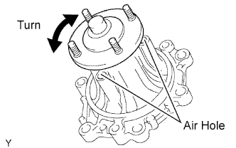
Visually check the water hole and air holes for coolant leakage.
If leakage is found, replace the water pump assembly.
-
Turn the pulley, and check that the pump bearing moves smoothly and quietly.
If it moves roughly or noisily, replace the water pump assembly.
-
-
SET NO. 1 CYLINDER TO TDC/COMPRESSION
-
Turn the crankshaft pulley and align its groove with the timing pointer.
-
Check that the valve lifters on the No. 1 cylinder are loose and valve lifters on the No. 4 are tight.
If not, turn the crankshaft one revolution (360°) and align the mark as above.
-
-
INSTALL TIMING BELT
Tech Tips
If reusing the timing belt, align the points marked during removal, and install the timing belt with the arrow pointing in the direction of engine revolution.
-
Remove any oil or water on each pulleys, and keep them clean.
-
Install the timing belt on the crankshaft timing and timing belt idlers.
-
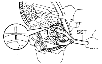
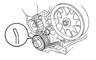
Using SST, slightly turn the injection pump drive pulley clockwise. Hang the timing belt on the pulley, and align the timing marks of the drive pulley and timing belt case.
- SST
- 09960-10010 ( 09962-01000, 09963-01000 )
-
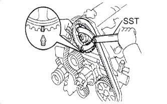
Using SST, slightly turn the camshaft timing pulley clockwise. Hang the timing belt on the timing pulley, and align the timing marks of the timing pulley and timing belt case.
- SST
- 09960-10010 ( 09962-01000, 09963-01000 )
-
Check that the timing belt has tension between the injection pump drive and camshaft timing pulleys.
-
Install the timing belt on the No. 2 timing belt idler.
-
-
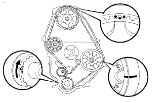
CHECK VALVE TIMING
-
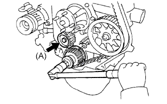
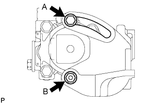
Loosen the No. 1 timing belt idler bolt (A), and stretch the timing belt.
-
Slowly turn the crankshaft pulley 2 revolutions from TDC to TDC.
Note
Always turn the crankshaft clockwise.
-
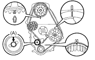
Check that each pulley aligns with the timing marks as shown in the illustration.
If the timing marks do not align, remove the timing belt and reinstall it.
-
Tighten the No. 1 timing belt idler bolt (A).
- Torque:
- 44 N*m { 450 kgf*cm, 33 ft.*lbf }
-
-
INSTALL TIMING BELT GUIDE
-
Install the belt guide with the cup side facing outward.
-
-
INSTALL TIMING BELT COVER
-
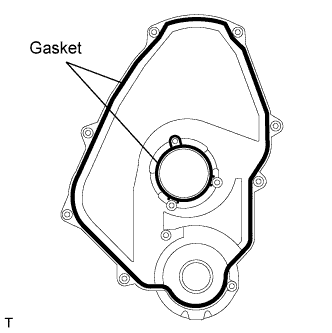
Install 2 new gaskets to the timing belt cover.
-
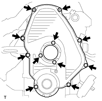
Install the timing belt cover with the 11 bolts.
- Torque:
- 11 N*m { 112 kgf*cm, 8 ft.*lbf }
-
-
INSTALL CRANKSHAFT PULLEY
-
Align the pulley set key with the key groove of the pulley, and slide the pulley to the crankshaft.
-
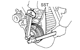
Using SST, install the new pulley bolt.
- SST
- 09213-54015 ( 91651-60855 )
- 09330-00021
- Torque:
- 235 N*m { 2,400 kgf*cm, 173 ft.*lbf }
-
-
INSTALL VANE PUMP DRIVE PULLEY
-
w/o Air conditioning:
Install the vane pump drive pulley and vane pump pulley spacer with the 4 bolts.
- Torque:
- 19 N*m { 195 kgf*cm, 14 ft.*lbf }
-
w/ Air conditioning:
Install the vane pump drive and No. 2 crankshaft pulleys with the 4 bolts.
- Torque:
- 18 N*m { 184 kgf*cm, 13 ft.*lbf }
-
-
INSTALL COMPRESSOR MOUNTING BRACKET (w/ Air Conditioning System)
-
Temporarily install the compressor mounting bracket with the 4 bolts.
-
Using several steps, uniformly install and tighten the 4 bolts.
- Torque:
- 85 N*m { 870 kgf*cm, 63 ft.*lbf }
-
Temporarily install the spacer with the bolt.
-
-
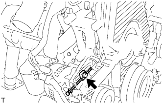
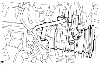
INSTALL COOLER COMPRESSOR (w/ Air Conditioning System)
-
Install the compressor with the 4 bolts.
- Torque:
- 50 N*m { 510 kgf*cm, 37 ft.*lbf }
-
-
INSTALL FAN & GENERATOR V BELT (w/o Air Conditioning System)
-
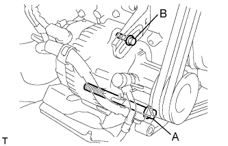
Install the V belt.
-
Using a bar, adjust the tension of the V belt.
-
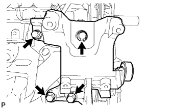
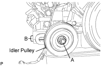
Tighten the bolts A and B.
- Torque:
- Bolt A
- 75 N*m { 765 kgf*cm, 55 ft.*lbf }
- Bolt B
- 18 N*m { 185 kgf*cm, 13 ft.*lbf }
-
Check the deflection of the V belt Click here.
-
-
INSTALL FAN & GENERATOR V BELT (w/ Air Conditioning System)
-
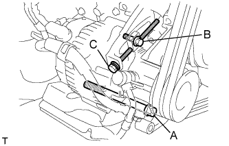
Install the V belt.
-
Tightening the bolt C, adjust the deflection of the V belt.
-
Tighten the bolts A and B.
- Torque:
- Bolt A
- 75 N*m { 765 kgf*cm, 55 ft.*lbf }
- Bolt B
- 18 N*m { 185 kgf*cm, 13 ft.*lbf }
-
Check the deflection of the V belt Click here.
-
-
TIGHTEN FAN PULLEY
-
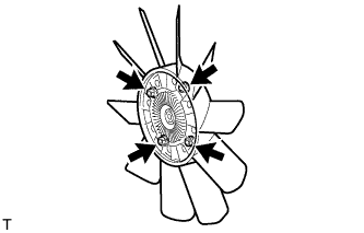
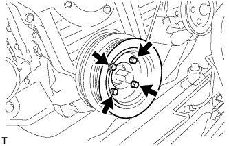
Install the fan to the coupling with the 4 nuts.
- Torque:
- 6.5 N*m { 66 kgf*cm, 58 in.*lbf }
-
-
INSTALL FAN SHROUD
-
Install the fan pulley to the water pump.
-
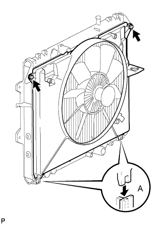
Install the shroud together with the coupling fan between the radiator and engine.
Note
Be careful not to damage the radiator core.
-
Install the fluid coupling fan to the fan pulley with the 4 nuts.
Tighten the nuts as much as possible by hand.
-
Attach the shroud's claws to the radiator as shown in A in the illustration.
-
Install the shroud with the 2 bolts.
- Torque:
- 5.0 N*m { 51 kgf*cm, 44 in.*lbf }
-
Install the fan and generator V belt, cooler compressor V belt and vane pump V belt Click here.
-
Tighten the 4 nuts of the fluid coupling fan.
- Torque:
- 19 N*m { 194 kgf*cm, 14 ft.*lbf }
-
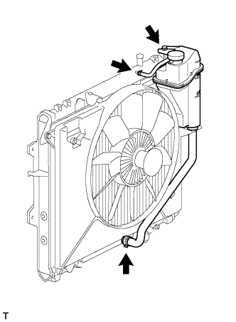
Install the radiator reservoir with the bolt.
- Torque:
- 5.0 N*m { 51 kgf*cm, 44 in.*lbf }
-
Connect the No. 1 and No. 2 water by-pass hoses to the tank upper and lower.
-
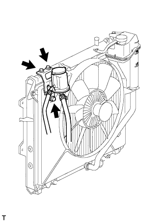
Install the oil reservoir with the 3 bolts.
- Torque:
- 5.0 N*m { 51 kgf*cm, 44 in.*lbf }
-
-
INSTALL COOLER COMPRESSOR V BELT (w/ Air Conditioning System)
-
Install the V belt.
-
Tightening the bolt B, adjust the tension of the V belt.
-
Tighten nut A.
- Torque:
- 39 N*m { 400 kgf*cm, 29 ft.*lbf }
-
Check the tension of the V belt Click here.
-
-
INSTALL VANE PUMP V BELT
-
Install the V belt.
-
Using a bar, adjust the tension of the V-ribbed belt.
-
Tighten the bolt A and nut B.
- Torque:
- Bolt (A)
- 48 N*m { 489 kgf*cm, 35 ft.*lbf }
- Nut (B)
- 64 N*m { 635 kgf*cm, 47 ft.*lbf }
-
Check the tension of the V belt Click here.
-
-
ADD ENGINE COOLANT
-
Tighten the radiator drain cock plug by hand.
-
Tighten the cylinder block drain cock plug.
- Torque:
- 57 N*m { 581 kgf*cm, 42 ft.*lbf }
-
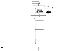
Fill the radiator with TOYOTA Super Long Life Coolant (SLLC) to the reservoir tank's FULL line.
Standard capacity 9.4 liters (9.9 US qts, 8.3 Imp. qts) Tech Tips
-
TOYOTA vehicles are filled with TOYOTA SLLC at the factory. In order to avoid damage to the engine cooling system and other technical problems, only use TOYOTA SLLC or similar high quality ethylene glycol based non-silicate, non-amine, non-nitrite, non-borate coolant with long-life hybrid organic acid technology (coolant with long-life hybrid organic acid technology consists of a combination of low phosphates and organic acids).
-
Please contact your TOYOTA dealer for further details.
Note
Never use water as a substitute for engine coolant.
-
-
Press the inlet and outlet radiator hoses several times by hand, and then check the level of the coolant.
If the coolant level drops below the FULL line, add TOYOTA SLLC to the FULL line.
-
Install the radiator reservoir cap.
-

Using a wrench, install the vent plug.
- Torque:
- 2.0 N*m { 20 kgf*cm, 18 in.*lbf }
-
Bleed air from the cooling system.
-
Warm up the engine until the thermostat opens. While the thermostat is open, circulate the coolant for several minutes.
-
Maintain the engine speed at 2,500 to 3,000 rpm.
-
Press the inlet and outlet radiator hoses several times by hand to bleed air.
CAUTION:
When pressing the radiator hoses:
-
Wear protective gloves.
-
Be careful as the radiator hoses are hot.
-
Keep your hands away from the radiator fan.
-
-
Stop the engine and wait until the coolant cools down to ambient temperature.
CAUTION:
Do not remove the radiator reservoir cap while the engine and radiator are still hot. Pressurized, hot engine coolant and steam may be released and cause serious burns.
-
-
After the coolant cools down, check that the coolant level is at the FULL line.
If the coolant level is below the low line, add TOYOTA SLLC to the FULL line.
-
-
INSPECT FOR ENGINE COOLANT LEAKS
-
The engine coolant level should be between the low and FULL lines when the engine is cold.
If the coolant is below the low line, check for leaks and add TOYOTA Super Long Life Coolant (SLLC) or similar high quality ethylene glycol based non-silicate, non-amine, non-nitrite, and non-borate coolant with long-life hybrid organic acid technology up to the FULL line.
Note
Never use water as a substitute for engine coolant.
-
-
CHECK FOR FUEL LEAKS
-
Check that there are no fuel leaks anywhere on the fuel system after performing maintenance.
Tech Tips
When checking for fuel leaks, make sure that there is pressure in fuel line.
-
-
CONNECT CABLE TO NEGATIVE BATTERY TERMINAL