LIGHTING SYSTEM Overhead Console Illumination Light Circuit
| DTC Code | DTC Name |
|---|---|
| Overhead Console Illumination Light Circuit |
DESCRIPTION
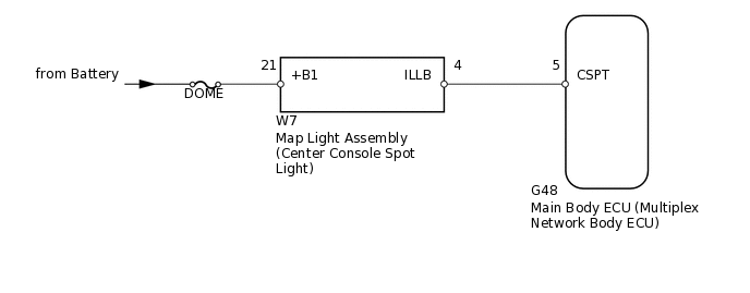
The main body ECU controls the center console spot light.
WIRING DIAGRAM
CAUTION / NOTICE / HINT
Inspect the fuses for circuits related to this system before performing the following inspection procedure.
PROCEDURE
PERFORM ACTIVE TEST USING INTELLIGENT TESTER (CENTER CONSOLE SPOT LIGHT)
Using the intelligent tester, perform the Active Test.
Body Electrical > Main Body > Active Test
Tester Display
Measurement Item
Control Range
Diagnostic Note
Cent Consol Spot LGT
Center console spot light
ON/OFF
-
OK
Center console spot light comes on.
Result
Result
OK
NG
INSPECT MAP LIGHT ASSEMBLY
-
Remove the map light.
Connect a positive (+) lead from the battery to terminal 21 (+B1) and a negative (-) lead to terminal 4 (ILLB).
Check that the center console spot light comes on.OK:
OK
Center console spot light comes on.
Result
Result
OK
NG
-
CHECK HARNESS AND CONNECTOR (BATTERY - MAP LIGHT ASSEMBLY)
-
*a
Front view of wire harness connector
(to Map Light Assembly)
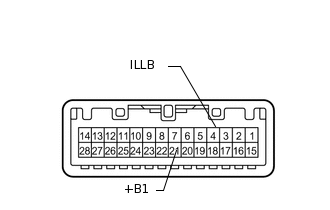
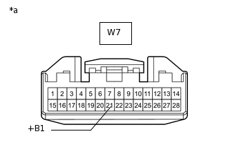
Disconnect the W7 map light connector.
Measure the voltage according to the value(s) in the table below.
Standard Voltage
Tester Connection
Condition
Specified Condition
W7-21 (+B1) - Body ground
Always
11 to 14 V
Result
Result
OK
NG
NG REPAIR OR REPLACE HARNESS OR CONNECTOR
-
CHECK HARNESS AND CONNECTOR
Disconnect the W7 map light connector.
Disconnect the G48 main body ECU connector.
Measure the resistance according to the value(s) in the table below.
Standard Resistance
Tester Connection
Condition
Specified Condition
W7-4 (ILLB) - G48-5 (CSPT)
Always
Below 1 Ω
W7-4 (ILLB) - Body ground
Always
10 kΩ or higher
Result
Result
OK
NG
NG REPAIR OR REPLACE HARNESS OR CONNECTOR