FRONT ACTIVE STABILIZER CONTROL ACTUATOR INSTALLATION
PROCEDURE
-
INSTALL FRONT STABILIZER BAR BUSHING LH
-
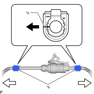
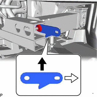
*a Cutout *b Stopper 
Front of the Vehicle 
Outside of the Vehicle Install the front stabilizer bar bushing LH to the front active stabilizer control actuator assembly as shown in the illustration.
Note
-
Install the front stabilizer bar bushing LH so that the cutout is facing the front of the vehicle.
-
Install the front stabilizer bar bushing RH onto the front active stabilizer control actuator assembly so that the stopper ring of the front active stabilizer control actuator assembly faces the outside of the vehicle.
-
-
-
INSTALL FRONT STABILIZER BAR BUSHING RH
Tech Tips
Perform the same procedure as for the LH side.
-
INSTALL FRONT NO. 2 STABILIZER BRACKET LH
-
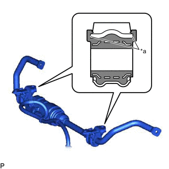
*a Groove Install the front No. 2 stabilizer bracket LH to the front stabilizer bar bushing LH.
Note
Check that the front No. 2 stabilizer bracket LH is securely seated in the groove of the front stabilizer bar bushing LH.
-
-
INSTALL FRONT NO. 2 STABILIZER BRACKET RH
Tech Tips
Perform the same procedure as for the LH side.
-
INSTALL FRONT NO. 1 STABILIZER BRACKET LH
-
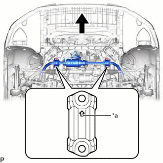
*a Arrow Mark Front of the Vehicle Install the front No. 1 stabilizer bracket LH to the front stabilizer bar bushing LH.
Note
Make sure to install the front No. 1 stabilizer bracket LH with its arrow facing the front of the vehicle.
-
-
INSTALL FRONT NO. 1 STABILIZER BRACKET RH
Tech Tips
Perform the same procedure as for the LH side.
-
INSTALL WIRE HARNESS CLAMP BRACKET
Tech Tips
Perform this procedure only when replacement of the wire harness clamp bracket is necessary.
-
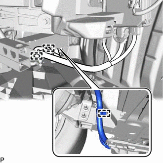
Engage the guide to install the wire harness clamp bracket.
-
Install the nut.
- Torque:
- 8.5 N*m { 87 kgf*cm, 75 in.*lbf }
-
Top of the Vehicle Outside of the Vehicle Install the No. 1 engine hanger with the nut as shown in the illustration.
- Torque:
- 25 N*m { 255 kgf*cm, 18 ft.*lbf }
-
-
INSTALL FRONT ACTIVE STABILIZER CONTROL ACTUATOR ASSEMBLY
-
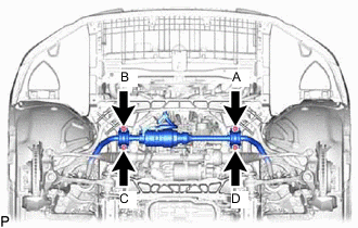
Install the front stabilizer bar with the 4 bolts and 4 nuts.
- Torque:
- 120 N*m { 1224 kgf*cm, 89 ft.*lbf }
Note
Temporarily tighten the bolt (A), (B) and then fully tighten the 4 bolts in the order of (C), (D), (A), and (B).
-
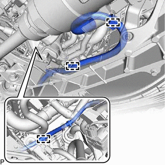
Engage the 3 clamps to install the wire harness.
-
Engage the 3 clamps to install the wire harness.
-
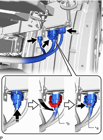
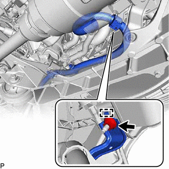
*a Lock of the Lock Lever *b Lock Lever Connect the 3 connectors to the active stabilizer control ECU assembly.
Tech Tips
When connecting a connector with lock lever, return the lock lever to its original position and securely push in the lock of the lock lever as shown in the illustration.
-
-
INSTALL FRONT STABILIZER LINK ASSEMBLY LH
-
Install the front stabilizer link assembly LH to the lower No. 2 suspension arm assembly LH and front stabilizer bar with the 2 nuts.
- Torque:
- 125 N*m { 1275 kgf*cm, 92 ft.*lbf }
Tech Tips
If the ball joint turns together with the nut, use a 8 mm hexagon wrench to hold the stud bolt.
-
-
INSTALL FRONT STABILIZER LINK ASSEMBLY RH
Tech Tips
Perform the same procedure as for the LH side.
-
INSTALL FRONT BUMPER ASSEMBLY
-
for Sport Package:
-
except Sport Package:
-
-
INSTALL STRUT BAR BRACKET SUPPORT SUB-ASSEMBLY
-
INSTALL FRONT SUSPENSION MEMBER BRACE
-
INSTALL NO. 2 ENGINE UNDER COVER ASSEMBLY
-
INSTALL TRANSMISSION UNDER COVER
-
INSTALL NO. 1 ENGINE UNDER COVER ASSEMBLY
-
CONNECT CABLE TO NEGATIVE BATTERY TERMINAL
Note
When disconnecting the cable, some systems need to be initialized after the cable is reconnected.
-
INSTALL LUGGAGE COMPARTMENT MAT SUB-ASSEMBLY
-
MOTOR ROTATION ANGLE SENSOR CALIBRATION (FRONT STABILIZER)