SHIFT LEVER ASSEMBLY ON-VEHICLE INSPECTION
PROCEDURE
INSPECT SHIFT LOCK SOLENOID
-
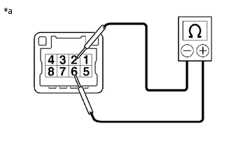
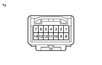
*a
Component without harness connected
(Shift Lever Assembly)
Disconnect the shift lever assembly connector.
Measure the resistance according to the value(s) in the table below.
Standard Resistance
Tester Connection
Condition
Specified Condition
2 - 6
20°C (68°F)
30 to 35 Ω
If the resistance is not as specified, replace the shift lock control unit assembly.
-
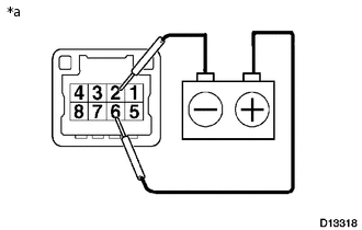
*a
Component without harness connected
(Shift Lever Assembly)
Check the solenoid operating sound when applying battery voltage across terminals 2 and 6.
Tip:If the solenoid does not operate, replace the shift lock control unit assembly.
Connect the shift lever assembly connector.
-
INSPECT TRANSMISSION SHIFT MAIN SWITCH
-
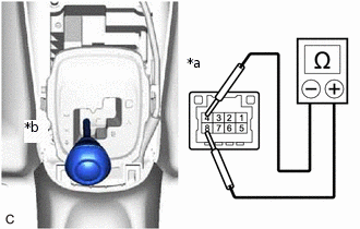
*a
Component without harness connected
(Shift Lever Assembly)
*b
M Position
Disconnect the shift lever assembly connector.
Move the shift lever to M.
Measure the resistance according to the value(s) in the table below.
Standard Resistance
Tester Connection
Shift Lever Position
Specified Condition
4 - 8
M
Below 1 Ω
If the resistance is not as specified, replace the shift lock control unit assembly.
-
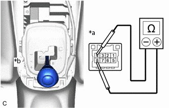
*a
Component without harness connected
(Shift Lever Assembly)
*b
E Position
Move the shift lever to E.
Measure the resistance according to the value(s) in the table below.
Standard Resistance
Tester Connection
Shift Lever Position
Specified Condition
4 - 8
E
10 kΩ or higher
If the result is not as specified, replace the shift lock control unit assembly.
Connect the shift lever assembly connector.
-
INSPECT SHIFT LEVER POSITION SENSOR
*a
Component without harness connected
(Shift Lever Position Sensor)
Disconnect the shift lever position sensor connector.
Measure the resistance according to the value(s) in the table below.
Standard Resistance
Tester Connection
Shift Lever Position
Specified Condition
4 - 9 - 10 - 13
R
Below 1 Ω
4 - 2 - 10 - 6
N
Below 1 Ω
4 - 2 - 3 - 13
E, M
Below 1 Ω
11 - 12
+
Below 1 Ω
11 - 5 - 12
M
10 kΩ or higher
11 - 5
-
Below 1 Ω
If the result is not as specified, replace the shift lever position sensor.
Connect the shift lever position sensor connector.