TIRE PRESSURE WARNING SYSTEM TC and CG Terminal Circuit
| DTC Code | DTC Name |
|---|---|
| TC and CG Terminal Circuit |
DESCRIPTION
DTC output mode is set by connecting terminals 13 (TC) and 4 (CG) of the DLC3. The DTCs are output by the blinking of the tire pressure warning light.
WIRING DIAGRAM
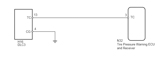
When each warning light blinks continuously, a ground short in the wiring of terminal TC of the DLC3 or an internal ground short in each ECU is suspected.
PROCEDURE
CHECK HARNESS AND CONNECTOR (DLC3 - ECU AND BODY GROUND)
Disconnect the tire pressure warning ECU and receiver N32 connector.
Measure the resistance according to the value(s) in the table below.
Standard Resistance
Tester Connection
Condition
Specified Condition
H16-13 (TC) - N32-3 (TC)
Always
Below 1 Ω
H16-13 (TC) or N32-3 (TC) - Body ground
Always
10 kΩ or higher
H16-4 (CG) - Body ground
Always
Below 1 Ω
REPAIR OR REPLACE HARNESS OR CONNECTOR OR EACH ECU