UPPER INSTRUMENT PANEL(for Sedan) REASSEMBLY
PROCEDURE
INSTALL NO. 1 DEFROSTER NOZZLE GARNISH
Install the No. 1 defroster nozzle garnish with the 8 screws <B>.

INSTALL NO. 1 SIDE DEFROSTER NOZZLE
-
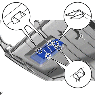
Engage the 5 claws to install the No. 1 side defroster nozzle.
-
INSTALL NO. 2 SIDE DEFROSTER NOZZLE
Tip:Use the same procedure as for the No. 1 side defroster nozzle.
INSTALL NO. 1 INSTRUMENT PANEL CUSHION
Remove the release paper from a new No. 1 instrument panel cushion.
Tip:After removing the release paper, keep the exposed adhesive free from foreign matter.
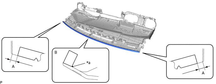
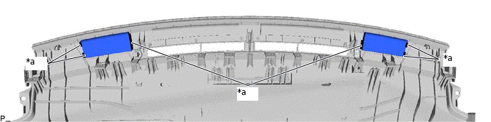
Install the No. 1 instrument panel cushion as shown in the illustration.
*a
Alignment Mark
-
-
Tip:Install the ends of the No. 1 instrument panel cushion so that they are within the standard dimension (A) shown in the illustration.
Install the No. 1 instrument panel cushion between the alignment mark and the edge of the upper instrument panel assembly (B).
Table 1. Standard Dimension Area
Dimension
A
0 to 10 mm (0 to 0.394 in.)
Remove the release paper from a new No. 1 instrument panel cushion.
Tip:After removing the release paper, keep the exposed adhesive free from foreign matter.
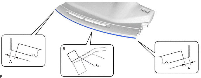
Install the No. 1 instrument panel cushion as shown in the illustration.
*a
Alignment Mark
-
-
Tip:Install the ends of the No. 1 instrument panel cushion so that they are within the standard dimension (A) shown in the illustration.
Install the No. 1 instrument panel cushion between the alignment mark and the edge of the upper instrument panel assembly (B).
Table 2. Standard Dimension Area
Dimension
A
0 to 10 mm (0 to 0.394 in.)
INSTALL NO. 4 INSTRUMENT PANEL CUSHION
Remove the release paper from 2 new No. 4 instrument panel cushions.
Tip:After removing the release paper, keep the exposed adhesive free from foreign matter.
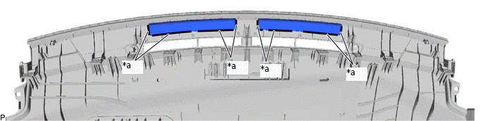
Install the 2 No. 4 instrument panel cushions.
*a
Marking
-
-
Tip:Install each No. 4 instrument panel cushion so that it is within the markings shown in the illustration.
INSTALL NO. 5 INSTRUMENT PANEL CUSHION
Remove the release paper from 2 new No. 5 instrument panel cushions.
Tip:After removing the release paper, keep the exposed adhesive free from foreign matter.
Install the 2 No. 5 instrument panel cushions.
*a
Marking
-
-
Tip:Install each No. 5 instrument panel cushion so that it is within the markings shown in the illustration.
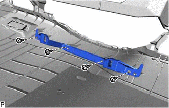
INSTALL NO. 2 INSTRUMENT PANEL WIRE
for Manual Air Conditioning System:
-
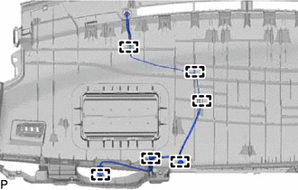
Engage the 6 clamps to install the No. 2 instrument panel wire.
-
for Automatic Air Conditioning System:
-
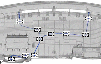
Engage the 10 clamps to install the No. 2 instrument panel wire.
-
INSTALL NAVIGATION ANTENNA ASSEMBLY (w/ Navigation System)
INSTALL NO. 2 INSTRUMENT PANEL CUSHION
for LHD:
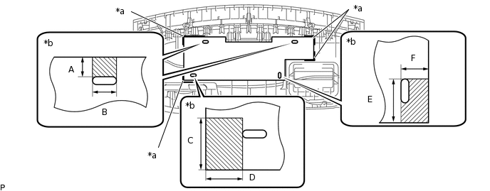
Using hot-melt glue, install a new No. 2 instrument panel cushion.
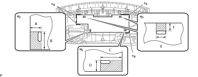
*a
Marking
*b
Hot-melt Glue Application Location
Tip:Install the No. 2 instrument panel cushion so that it is within the markings shown in the illustration.
Table 3. Standard Dimension Area
Dimension
A
35 mm (1.3780 in.)
B
45 mm (1.7717 in.)
C
68 mm (2.6772 in.)
D
35 mm (1.3780 in.)
E
30 mm (1.1811 in.)
F
25 mm (0.9843 in.)
for RHD:
Using hot-melt glue, install a new No. 2 instrument panel cushion.
*a
Marking
*b
Hot-melt Glue Application Location
Tip:Install the No. 2 instrument panel cushion so that it is within the markings shown in the illustration.
Table 4. Standard Dimension Area
Dimension
A
25 mm (0.9843 in.)
B
30 mm (1.1811 in.)
C
50 mm (1.9685 in.)
D
38 mm (1.4961 in.)
E
45 mm (1.7717 in.)
F
35 mm (1.3780 in.)
INSTALL INSTRUMENT CLUSTER FINISH PANEL RETAINER
-
Install the instrument cluster finish panel retainer with the 4 screws <B>.
-
INSTALL CENTER INSTRUMENT PANEL REGISTER ASSEMBLY
-
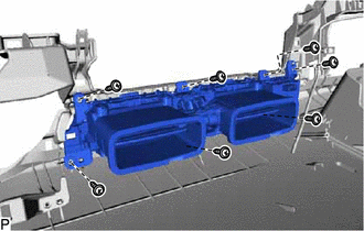
Install the center instrument panel register assembly with the 7 screws <B>.
-
Connect the connector.
-
INSTALL AUTOMATIC LIGHT CONTROL SENSOR (w/ Automatic Light Control System)
INSTALL COOLER (SOLAR SENSOR) THERMISTOR (for Automatic Air Conditioning System)
INSTALL INSTRUMENT PANEL PASSENGER AIRBAG ASSEMBLY
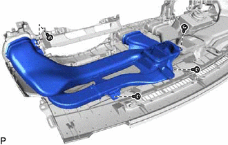
INSTALL NO. 2 HEATER TO REGISTER DUCT
-
Install the No. 2 heater to register duct with the 3 screws <B>.
-
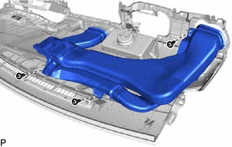
INSTALL NO. 1 HEATER TO REGISTER DUCT
-
Install the No. 1 heater to register duct with the 4 screws <B>.
-
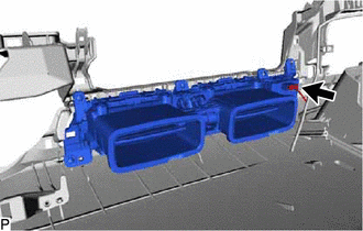
INSTALL DEFROSTER NOZZLE ASSEMBLY
-
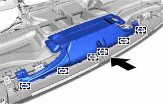
Engage the 6 guides as shown in the illustration.
-
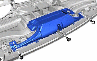
Install the defroster nozzle assembly with the 3 screws <B>.
-