HYBRID BATTERY SYSTEM, Diagnostic DTC:P0A80-123
| DTC Code | DTC Name |
|---|---|
| P0A80-123 | Replace Hybrid Battery Pack |
DESCRIPTION
-
The HV battery uses lithium-ion batteries and does not require external charging. The hybrid vehicle control ECU controls the SOC (state of charge) of the HV battery at a constant level during driving. The HV battery is composed of 56 modules, and each module consists of seven 3.6 V cells in series. The battery smart unit monitors battery block voltage at 7 locations.
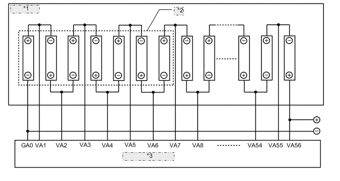
*1 HV Battery *2 Battery Block *3 Battery Smart Unit 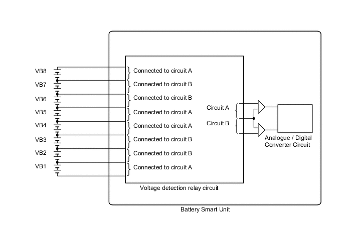
DTC No. INF Code DTC Detection Condition Trouble Area P0A80 123
-
Battery cell internal resistance value is out of the standard range (1 trip detection)
-
Difference between each HV battery block capacity is larger than the standard (1 trip detection)
-
Differences in voltage between each battery block when the power switch is on (IG) and off is larger than the standard (2 trip detection)
-
HV battery
-
Battery smart unit
Tech Tips
-
P0A80-123 will not be set unless the vehicle is driven for approximately 10 minutes after clearing the DTC. (As 2 trip detection logic is used, check for DTCs including pending DTCs.)
-
DTC P0A80-123 is stored when a malfunction is detected in the HV battery or battery smart unit. If the HV supply battery is malfunctioning, the malfunction may not be reproduced when the condition of HV supply battery changes due to difference in the driving load (amperage), battery SOC and battery temperature. Therefore, use the freeze frame data when performing a repair.
-
In order to ensure HV battery performance, appropriate cooling performance must be maintained. Perform the following items as necessary:
-
Make sure the air intake port is not blocked.
-
Make sure there are no gaps between the connecting parts of the ducts.
-
CAUTION / NOTICE / HINT
CAUTION:
-
When disposing of an HV battery, make sure to return it through an authorized collection agent who is capable of handling it safely. If the HV battery is returned via the manufacturer specified route, it will be returned properly and in a safe manner by an authorized collection agent.
-
Before returning the HV battery, make sure to perform a recovery inspection Click here
-
Make a note of the output DTCs as some of them may be necessary for recovery inspection of the HV battery.
PROCEDURE
-
CHECK DTC OUTPUT (HYBRID CONTROL)
-
Connect the GTS to the DLC3.
-
Turn the power switch on (IG).
-
Enter the following menus: Powertrain / Hybrid Control / Trouble Codes.
-
Read output DTCs.
Result Result Proceed to P31AB-123 is not output A P31AB-123 is output B -
Turn the power switch off.
B 
GO TO DTC CHART (P31AB-123) Click here
A 
-
-
CHECK DTC OUTPUT (HYBRID CONTROL)
-
Connect the GTS to the DLC3.
-
Turn the power switch on (IG).
-
Enter the following menus: Powertrain / Hybrid Control / Trouble Codes.
-
Read output DTCs Click here.
Result Result Proceed to P0AFC-123 is not output. A P0AFC-123 is also output. B -
Turn the power switch off.
B
GO TO DTC CHART (P0AFC-123) Click here
A
-
-
CHECK FREEZE FRAME DATA
-
Connect the GTS to the DLC3.
-
Turn the power switch on (IG).
-
Enter the following menus: Powertrain / Hybrid Control / Trouble Codes.
-
Read output DTCs.
-
Using the GTS, make a note of the freeze frame data item "Battery Block Vol -V01 to V08".
-
Compare the freeze frame data item "Battery Block Vol -V01 to V08" values with those shown in the following combination tables.
Table 1 Circuit A Battery Block Circuit B Battery Block Condition Battery Block Vol-V01 (VB1) Battery Block Vol-V02 (VB2) "Battery Block Vol - V01" - "Battery Block Vol - V02" = 0.6 V or more Battery Block Vol-V04 (VB4) Battery Block Vol-V03 (VB3) "Battery Block Vol - V04" - "Battery Block Vol - V03" = 0.6 V or more Battery Block Vol-V05 (VB5) Battery Block Vol-V06 (VB6) "Battery Block Vol - V05" - "Battery Block Vol - V06" = 0.6 V or more Battery Block Vol-V08 (VB8) Battery Block Vol-V07 (VB7) "Battery Block Vol - V08" - "Battery Block Vol - V07" = 0.6 V or more Table 2 Circuit A Battery Block Circuit B Battery Block Condition Battery Block Vol-V01 (VB1) Battery Block Vol-V02 (VB2) "Battery Block Vol - V02" - "Battery Block Vol - V01" = 0.6 V or more Battery Block Vol-V04 (VB4) Battery Block Vol-V03 (VB3) "Battery Block Vol - V03" - "Battery Block Vol - V04" = 0.6 V or more Battery Block Vol-V05 (VB5) Battery Block Vol-V06 (VB6) "Battery Block Vol - V06" - "Battery Block Vol - V05" = 0.6 V or more Battery Block Vol-V08 (VB8) Battery Block Vol-V07 (VB7) "Battery Block Vol - V07" - "Battery Block Vol - V08" = 0.6 V or more 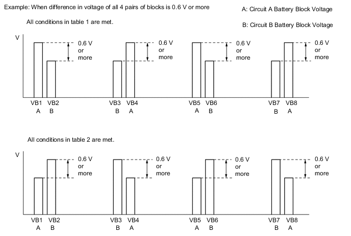
Result Result Proceed to All conditions in table 1 are met. A All conditions in table 2 are met. Other than above. B -
Turn the power switch off.
A
REPLACE BATTERY SMART UNIT Click here
B
-
-
CHECK BATTERY SMART UNIT
Note
Make sure to use tester probes with a diameter of approximately 0.5 mm (0.0197 in.) when measuring the resistance.
-
Remove the battery smart unit.
-
Measure the resistance according to the value(s) in the table below.
Tech Tips
It is only necessary measure the resistance of the battery smart unit at the terminals which relate to the lower voltage battery block of pairs of battery blocks for which the difference in voltage in the freeze frame data was 0.6 V or more.
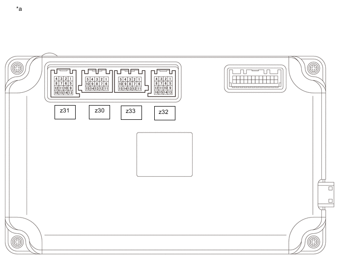
*a Component without harness connected
(Battery Smart Unit)
- - Standard Resistance (When Value of Battery Block Vol-V01 (VB1) is Low) Tester Connection
(Tester Probe Polarity)
Condition Specified Condition z32-13 (GA0) (-) - z32-9 (VA1) (+) Always 50 kΩ or higher z32-9 (VA1) (-) - z32-5 (VA2) (+) Always 50 kΩ or higher z32-5 (VA2) (-) - z32-1 (VA3) (+) Always 50 kΩ or higher z32-1 (VA3) (-) - z32-14 (VA4) (+) Always 50 kΩ or higher z32-14 (VA4) (-) - z32-10 (VA5) (+) Always 50 kΩ or higher z32-10 (VA5) (-) - z32-6 (VA6) (+) Always 50 kΩ or higher z32-6 (VA6) (-) - z32-2 (VA7) (+) Always 50 kΩ or higher z32-13 (GA0) (-) -z32-2 (VA7) (+) Always 350 kΩ or higher Standard Resistance (When Value of Battery Block Vol-V02 (VB2) is Low) Tester Connection
(Tester Probe Polarity)
Condition Specified Condition z32-2 (VA7) (-) - z32-15 (VA8) (+) Always 50 kΩ or higher z32-15 (VA8) (-) - z32-11 (VA9) (+) Always 50 kΩ or higher z32-11 (VA9) (-) - z32-7 (VA10) (+) Always 50 kΩ or higher z32-7 (VA10) (-) - z32-16 (VA11) (+) Always 50 kΩ or higher z32-16 (VA11) (-) - z32-12 (VA12) (+) Always 50 kΩ or higher z32-12 (VA12) (-) - z32-8 (VA13) (+) Always 50 kΩ or higher z32-8 (VA13) (-) - z32-4 (VA14) (+) Always 50 kΩ or higher z32-2 (VA7) (-) - z32-4 (VA14) (+) Always 350 kΩ or higher Standard Resistance (When Value of Battery Block Vol-V03 (VB3) is Low) Tester Connection
(Tester Probe Polarity)
Condition Specified Condition z33-11 (GA1) (-) - z33-6 (VA15) (+) Always 50 kΩ or higher z33-6 (VA15) (-) - z33-1 (VA16) (+) Always 50 kΩ or higher z33-1 (VA16) (-) - z33-12 (VA17) (+) Always 50 kΩ or higher z33-12 (VA17) (-) - z33-7 (VA18) (+) Always 50 kΩ or higher z33-7 (VA18) (-) - z33-2 (VA19) (+) Always 50 kΩ or higher z33-2 (VA19) (-) - z33-13 (VA20) (+) Always 50 kΩ or higher z33-13 (VA20) (-) - z33-8 (VA21) (+) Always 50 kΩ or higher z33-11 (GA1) (-) - z33-8 (VA21) (+) Always 350 kΩ or higher Standard Resistance (When Value of Battery Block Vol-V04 (VB4) is Low) Tester Connection
(Tester Probe Polarity)
Condition Specified Condition z33-8 (VA21) (-) - z33-3 (VA22) (+) Always 50 kΩ or higher z33-3 (VA22) (-) - z33-14 (VA23) (+) Always 50 kΩ or higher z33-14 (VA23) (-) - z33-9 (VA24) (+) Always 50 kΩ or higher z33-9 (VA24) (-) - z33-4 (VA25) (+) Always 50 kΩ or higher z33-4 (VA25) (-) - z33-15 (VA26) (+) Always 50 kΩ or higher z33-15 (VA26) (-) - z33-10 (VA27) (+) Always 50 kΩ or higher z33-10 (VA27) (-) - z33-5 (VA28) (+) Always 50 kΩ or higher z33-8 (VA21) (-) - z33-5 (VA28) (+) Always 350 kΩ or higher Standard Resistance (When Value of Battery Block Vol-V05 (VB5) is Low) Tester Connection
(Tester Probe Polarity)
Condition Specified Condition z30-11 (GA2) (-) - z30-6 (VA29) (+) Always 50 kΩ or higher z30-6 (VA29) (-) - z30-1 (VA30) (+) Always 50 kΩ or higher z30-1 (VA30) (-) - z30-12 (VA31) (+) Always 50 kΩ or higher z30-12 (VA31) (-) - z30-7 (VA32) (+) Always 50 kΩ or higher z30-7 (VA32) (-) - z30-2 (VA33) (+) Always 50 kΩ or higher z30-2 (VA33) (-) - z30-13 (VA34) (+) Always 50 kΩ or higher z30-13 (VA34) (-) - z30-8 (VA35) (+) Always 50 kΩ or higher z30-11 (GA2) (-) - z30-8 (VA35) (+) Always 350 kΩ or higher Standard Resistance (When Value of Battery Block Vol-V06 (VB6) is Low) Tester Connection
(Tester Probe Polarity)
Condition Specified Condition z30-8 (VA35) (-) - z30-3 (VA36) (+) Always 50 kΩ or higher z30-3 (VA36) (-) - z30-14 (VA37) (+) Always 50 kΩ or higher z30-14 (VA37) (-) - z30-9 (VA38) (+) Always 50 kΩ or higher z30-9 (VA38) (-) - z30-4 (VA39) (+) Always 50 kΩ or higher z30-4 (VA39) (-) - z30-15 (VA40) (+) Always 50 kΩ or higher z30-15 (VA40) (-) - z30-10 (VA41) (+) Always 50 kΩ or higher z30-10 (VA41) (-) - z30-5 (VA42) (+) Always 50 kΩ or higher z30-8 (VA35) (-) - z30-5 (VA42) (+) Always 350 kΩ or higher Standard Resistance (When Value of Battery Block Vol-V07 (VB7) is Low) Tester Connection
(Tester Probe Polarity)
Condition Specified Condition z31-13 (GA3) (-) - z31-9 (VA43) (+) Always 50 kΩ or higher z31-9 (VA43) (-) - z31-5 (VA44) (+) Always 50 kΩ or higher z31-5 (VA44) (-) - z31-1 (VA45) (+) Always 50 kΩ or higher z31-1 (VA45) (-) - z31-14 (VA46) (+) Always 50 kΩ or higher z31-14 (VA46) (-) - z31-10 (VA47) (+) Always 50 kΩ or higher z31-10 (VA47) (-) - z31-6 (VA48) (+) Always 50 kΩ or higher z31-6 (VA48) (-) - z31-2 (VA49) (+) Always 50 kΩ or higher z31-13 (GA3) (-) - z31-2 (VA49) (+) Always 350 kΩ or higher Standard Resistance (When Value of Battery Block Vol-V08 (VB8) is Low) Tester Connection
(Tester Probe Polarity)
Condition Specified Condition z31-2 (VA49) (-) - z31-15 (VA50) (+) Always 50 kΩ or higher z31-15 (VA50) (-) - z31-11 (VA51) (+) Always 50 kΩ or higher z31-11 (VA51) (-) - z31-7 (VA52) (+) Always 50 kΩ or higher z31-7 (VA52) (-) - z31-16 (VA53) (+) Always 50 kΩ or higher z31-16 (VA53) (-) - z31-12 (VA54) (+) Always 50 kΩ or higher z31-12 (VA54) (-) - z31-8 (VA55) (+) Always 50 kΩ or higher z31-8 (VA55) (-) - z31-4 (VA56) (+) Always 50 kΩ or higher z31-2 (VA49) (-) - z31-4 (VA56) (+) Always 350 kΩ or higher Note
-
Make sure to check the polarity of each terminal (positive (+) or negative (-)) before connecting a tester.
-
Read the resistance after the value has stabilized.
-
In order to avoid damaging the terminals of the battery smart unit, make sure to use tester probes with a diameter of approximately 0.5 mm (0.0197 in.) when measuring the resistance of the battery smart unit.
-
-
Install the battery smart unit.
Result Result Proceed to All measured values were within specified range. A Other than above. B
A
REPLACE HV BATTERY Click here
B
-
-
REPLACE BATTERY SMART UNIT
NEXT
REPLACE HV BATTERY Click here