FUEL SYSTEM
-
FUNCTION OF MAIN COMPONENTS
-
The D-4S system has the following components and functions:
Component Function Fuel Pump (for Low Pressure Side) Sends fuel (420 kPa) from the fuel tank assembly to the fuel pump assembly (for high pressure side) and port fuel injector assembly. Fuel Pump Assembly (for High Pressure Side) Increases the pressure of the fuel from the fuel pump assembly (for low pressure side) to a pressure of 4.0 to 20 MPa and sends it to the fuel delivery pipe with sensor assembly (for direct injection). Spill Control Valve (built-in Fuel Pump Assembly (for High Pressure Side)) Closes and opens the fuel flow path to the high-pressure fuel system in accordance with signals from the ECM. Fuel Pressure Pulsation Damper (built-in Fuel Pump Assembly (for High Pressure Side)) Reduces fuel pressure fluctuation (pulsation) and noise. Fuel Delivery Pipe Sub-assembly (for Port Injection) Delivers the low-pressure fuel to the port fuel injector assembly. Fuel Delivery Pipe with Sensor Assembly (for Direct Injection) Delivers the high-pressure fuel to the direct fuel injector assembly. Fuel Pressure Sensor Senses the fuel pressure and outputs a signal to the ECM. Port Fuel Injector Assembly Injects a calculated (by the ECM) quantity of 420 kPa (low pressure) fuel into the intake port. Direct Fuel Injector Assembly Injects a calculated (by the ECM) quantity of 4.0 to 20 MPa (high pressure) fuel directly into the combustion chamber. ECM Depending on the vehicle condition, and based on signals from various sensors, the ECM calculates the optimal injection timing and volume, and controls the direct fuel injector assembly and fuel pump assembly (for high pressure side).
-
-
FUNCTION
-
The Direct injection 4-stroke gasoline engine Superior version (D-4S) system has both direct type fuel injection, which directly injects high-pressure fuel into the combustion chamber, and port type fuel injection, which injects fuel into the intake port. The system optimally controls the fuel injectors for direct injection and port injection according to engine load.
-
In low to medium engine load ranges, both direct type and port type fuel injections are used together or one of them is used to create homogeneous mixed air, thus contributing to stable combustions. With this, the system achieves low fuel consumption and low emissions. In addition, in high engine load ranges, only the direct type fuel injection is used to cool down the intake air with the chilling effect of vapors in the fuel which is injected into the cylinder, improving charging efficiency and anti-knock properties.
-
Immediately after the engine is started in cold state, the fuel injector assembly on the port side is selected for the injection aiming at homogenizing the mixture in the combustion chamber. Next, the fuel injector assembly on the cylinder injection side performs fuel injection during the compression process in order to stratify the mixture layers around the spark plug. This formation not only enables a substantial retardation of ignition timing but also raises the in exhaust gas temperature, which facilitates the warm-up of the catalyst following a cold start.
-
A high-pressure single slit-nozzle injector is used as the direct fuel injector assembly. The fuel atomized by this injector is injected into the combustion chamber via the slit, spreading in a fan shaped pattern and combines with a large volume of intake air. The intake air will swirl in a vertical direction and promote mixture with the fuel, contributing to higher performance and higher output.
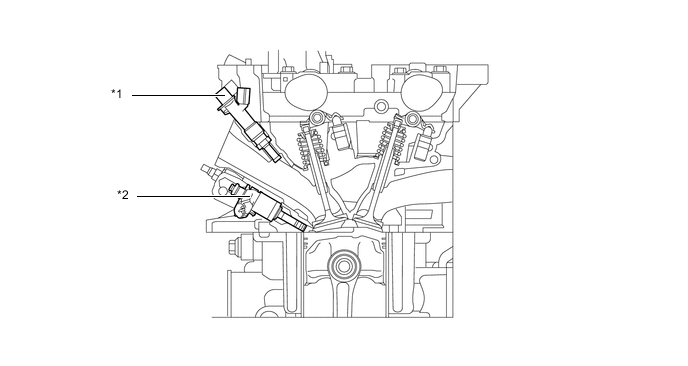
*1 Port Fuel Injector Assembly *2 Direct Fuel Injector Assembly
-