FRONT BODY PILLAR(for Type B) CUT AND JOIN REPLACEMENT SECTIONS (PATTERN 2)
-
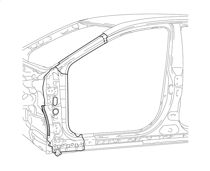
With the cowl top side panel assembly removed.
-
REMOVAL
Symbol Meaning 
Remove Weld Points 
Remove Weld Points 
Remove Weld Points 
Cut and Join Location 
Cut Location for Supply Parts
-
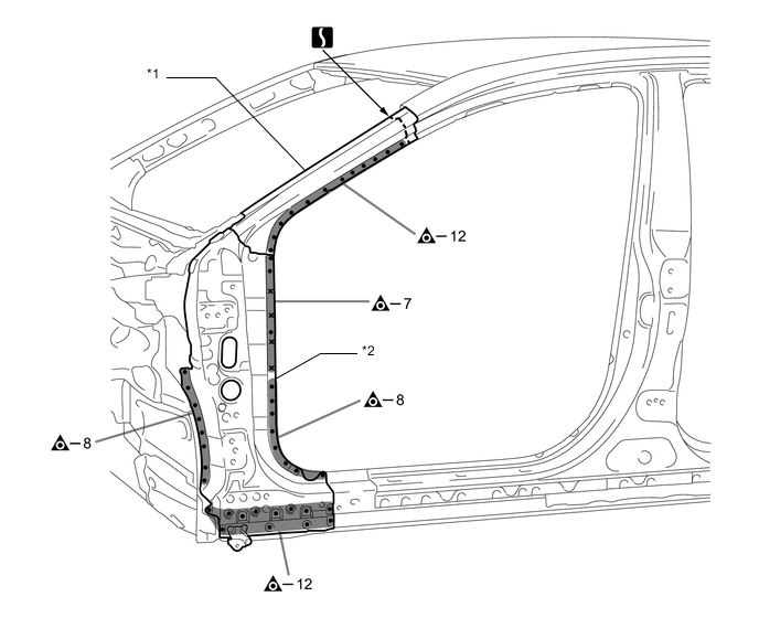
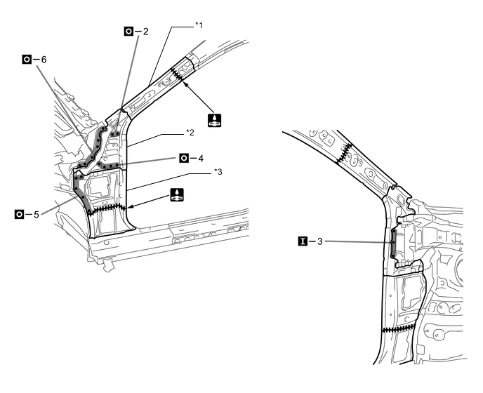
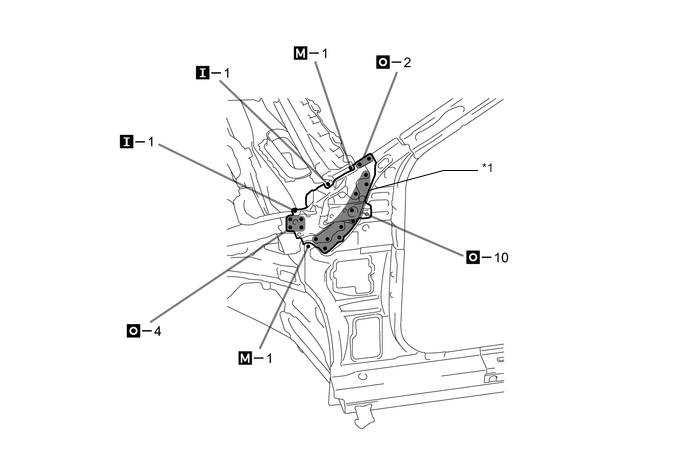
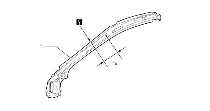
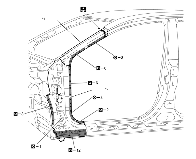
Remove the front body pillar upper outer.
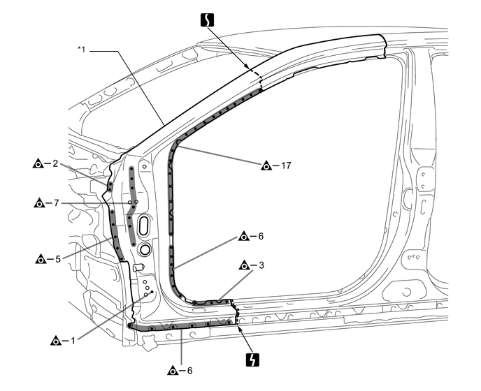
*1 FRONT BODY PILLAR UPPER OUTER - - 
Laser Screw Welding - - 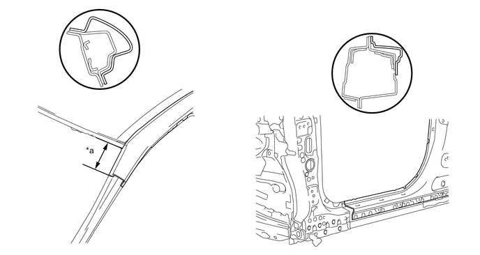
*a 170 mm (6.69 in.) - - 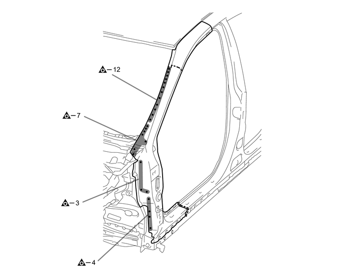
-
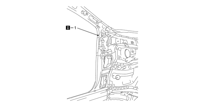
Roughly cut open the panel so that the adhesive can be reached. Cut through the adhesive with a cut chisel to remove the panel.
Tech Tips
In cases where the adhesive cannot be removed with a cut chisel, heat the adhesive with an industrial heater gun or gas burner taking care not to cause panel deformation by overheating.

Adhesive - - -
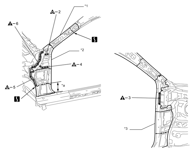
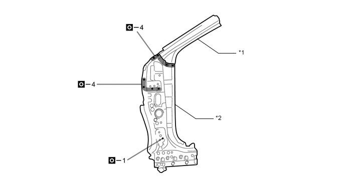
Remove the front body pillar reinforce sub-assembly lower and roof side rail.
*1 ROOF SIDE RAIL *2 FRONT BODY PILLAR REINFORCE SUB-ASSEMBLY LOWER Laser Screw Welding - - 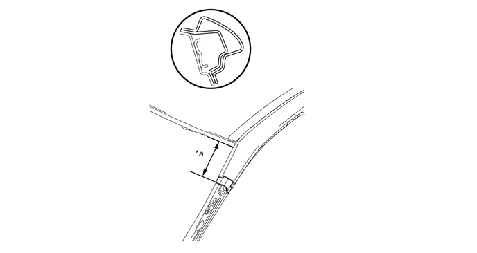
*a 190 mm (7.48 in.) - - 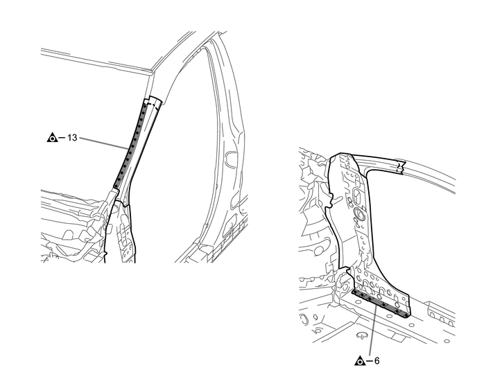
-
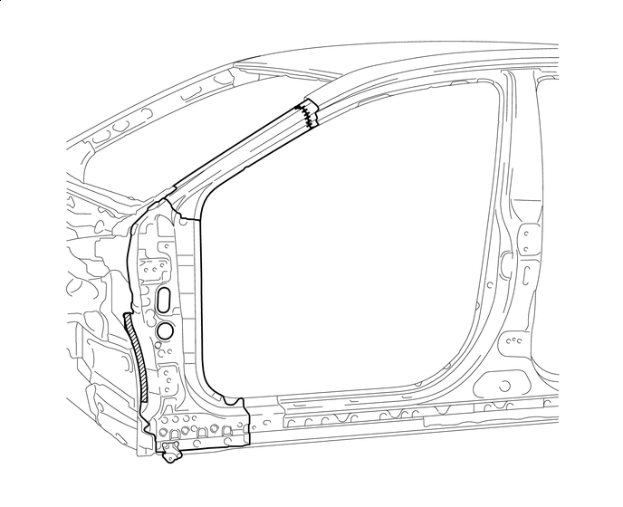
Remove the cowl top side panel sub-assembly.
*1 COWL TOP SIDE PANEL SUB-ASSEMBLY - - -
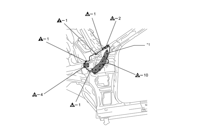
Remove the roof side rail sub-assembly inner, front body pillar lower inner and cowl side panel.
*1 ROOF SIDE RAIL SUB-ASSEMBLY INNER *2 FRONT BODY PILLAR LOWER INNER *3 COWL SIDE PANEL - - *a 135 mm (5.31 in.) - - 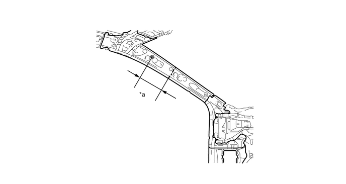
*a 240 mm (9.45 in.) - - -
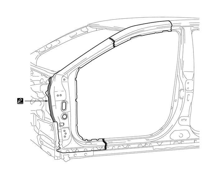
When replace only the outer panel, please cut off a necessary range depending on a damage range.
-
Carefully cut the outer panel so not to damage the reinforcement.
-
Make sure that butt welding does not heat-affect the reinforcement when welding the outer panel.
-
-
-
INSTALLATION
Symbol Meaning 
Spot Weld 
Plug Weld 
Plug Weld 
Plug Weld Cut and Join Location 
Fillet Weld 
Butt Weld 
Body Sealer
-
Inspect the fitting of the related parts around the new parts before welding. This affects the appearance of the finish.
-
Temporarily install the new parts and measure each part of the new parts in accordance with the body dimension diagram. (See the body dimensions)
-
If the entire supply part is not needed, remove the part of the supply part that is needed.
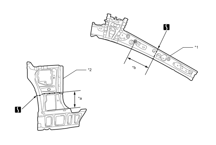
*1 ROOF SIDE RAIL SUB-ASSEMBLY INNER *2 COWL SIDE PANEL *a 135 mm (5.31 in.) *b 240 mm (9.45 in.) -
Before temporarily installing the new parts, weld the roof side rail sub-assembly inner, front body pillar lower inner and cowl side panel with the standard number of welding points.
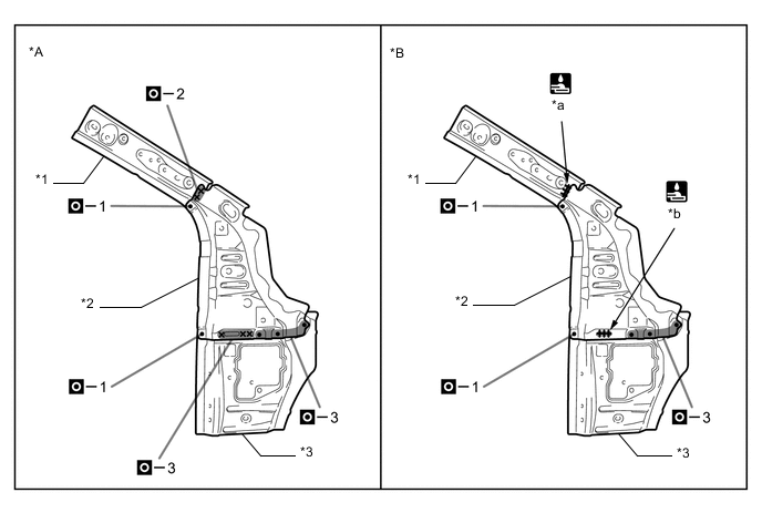
*A PATTERN 1 *B PATTERN 2 *1 ROOF SIDE RAIL SUB-ASSEMBLY INNER *2 FRONT BODY PILLAR LOWER INNER *3 COWL SIDE PANEL - - *a 15 mm (0.59 in.) *b 25 mm (0.98 in.) Laser Screw Welding - - -
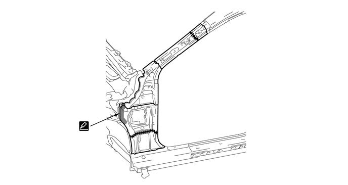
Before installing a new part, apply body sealer.
Tech Tips
Apply body sealer in an even, continuous bead.
-
Weld the roof side rail sub-assembly inner, front body pillar lower inner and cowl side panel to the vehicle side.
*1 ROOF SIDE RAIL SUB-ASSEMBLY INNER *2 FRONT BODY PILLAR LOWER INNER *3 COWL SIDE PANEL - - -
Before installing a new part, apply body sealer.
Tech Tips
Apply body sealer in an even, continuous bead.
-
Weld the cowl top side panel sub-assembly to the vehicle side.
*1 COWL TOP SIDE PANEL SUB-ASSEMBLY - - -
If the entire supply part is not needed, remove the part of the supply part that is needed.
*1 ROOF SIDE RAIL - - *a 70 mm (2.76 in.) - - -
Before temporarily installing the new parts, weld the front body pillar reinforce sub-assembly lower and roof side rail with the standard number of welding points.
*1 ROOF SIDE RAIL *2 FRONT BODY PILLAR REINFORCE SUB-ASSEMBLY LOWER -
Apply adhesive (3MTMAutomixTMPanel Bonding Adhesive #8115).
Tech Tips
-
Apply a light coat of adhesive around the plug welding points.
-
Apply enough adhesive to the panels.
Adhesive - - -
-
Weld the front body pillar reinforce sub-assembly lower and roof side rail to the vehicle side.
*1 ROOF SIDE RAIL *2 FRONT BODY PILLAR REINFORCE SUB-ASSEMBLY LOWER Laser Screw Welding - - 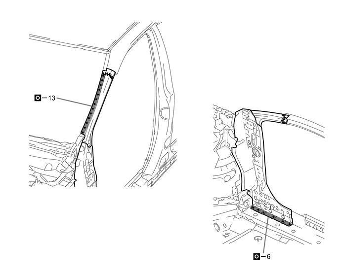
-
Before installing a new part, apply body sealer.
Tech Tips
Apply body sealer in an even, continuous bead.
-
Weld the front body pillar upper outer to the vehicle side.

*1 FRONT BODY PILLAR UPPER OUTER - - Laser Screw Welding - - 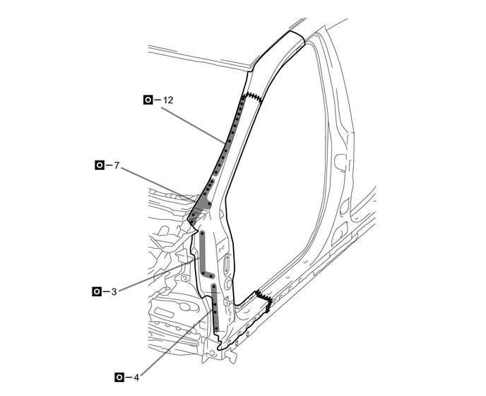
-
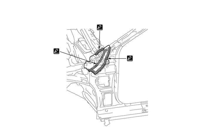
After welding, apply the foamed sealing material to the corresponding parts. (See the painting/coating)
-
After welding, apply body sealer to the corresponding parts. (See the painting/coating)
-
After applying the top coat, apply anti-rust agent to the internal panel portion of the closed section structural weld points.
-