METER / GAUGE SYSTEM Tachometer Malfunction
DESCRIPTION
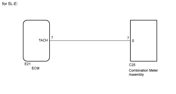
In this circuit, the combination meter assembly receives engine speed signals from the ECM. The meter CPU displays the engine speed, which is calculated based on the data received from the ECM.
WIRING DIAGRAM
INSPECTION PROCEDURE
PROCEDURE
-
CHECK COMBINATION METER ASSEMBLY
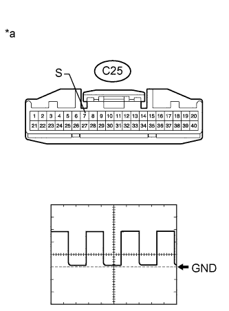
Text in Illustration *a Front view of wire harness connector
(to Combination Meter Assembly)
-
Disconnect the C25 combination meter assembly connector.
-
Using an oscilloscope, check the signal waveform of the meter.
Item Condition Tester Connection C25-7 (S) - Body ground Tool Setting 5 V/DIV., 10 msec./DIV. Condition Engine idling OK The waveform displayed is as shown in the illustration. Tech Tips
As the engine speed increases, the wavelength shortens.
NG 
CHECK HARNESS AND CONNECTOR (COMBINATION METER ASSEMBLY - ECM) Click here
OK 
REPLACE COMBINATION METER ASSEMBLY Click here
-
-
CHECK HARNESS AND CONNECTOR (COMBINATION METER ASSEMBLY - ECM)
-
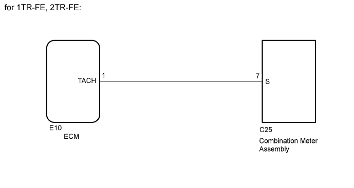
*1: for 1TR-FE, 2TR-FE
-
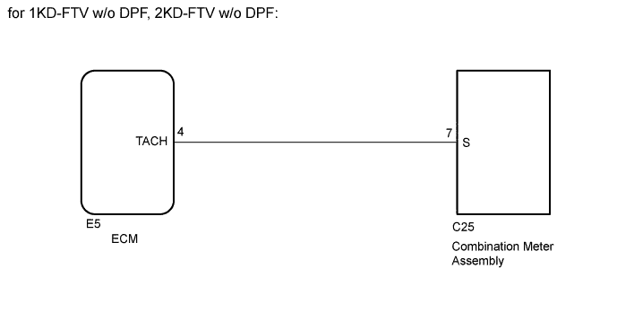
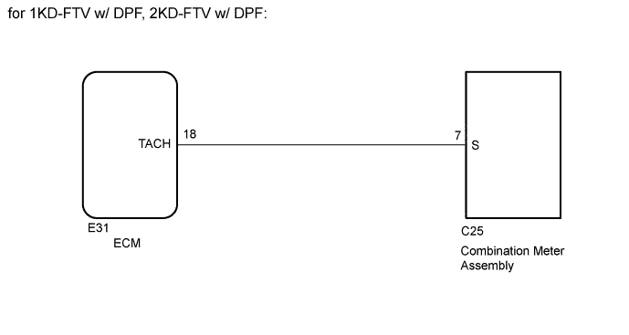
*2: for 1KD-FTV, 2KD-FTV
-
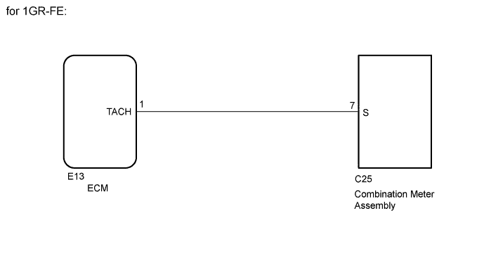
*3: for 1GR-FE
-
*4: for 5L-E
-
Disconnect the C25 combination meter assembly connector.
-
Disconnect the E10*1 or E5*2 or E13*3 or E21*4 ECM connector.
-
Measure the resistance according to the value(s) in the table below.
Standard Resistance for 1TR-FE, 2TR-FE Tester Connection Condition Specified Condition C25-7 (S) - E10-1 (TACH) Always Below 1 Ω C25-7 or E10-1 (TACH) - Body ground Always 10 kΩ or higher for 1KD-FTV w/o DPF, 2KD-FTV w/o DPF Tester Connection Condition Specified Condition C25-7 (S) - E5-4 (TACH) Always Below 1 Ω C25-7 (S) or E5-4 (TACH) - Body ground Always 10 kΩ or higher for 1KD-FTV w/ DPF, 2KD-FTV w/ DPF Tester Connection Condition Specified Condition C25-7 (S) - E31-18 (TACH) Always Below 1 Ω C25-7 (S) or E31-18 (TACH) - Body ground Always 10 kΩ or higher for 1GR-FE Tester Connection Condition Specified Condition C25-7 (S) - E13-1 (TACH) Always Below 1 Ω C25-7 or E13-1 (TACH) - Body ground Always 10 kΩ or higher for 5L-E Tester Connection Condition Specified Condition C25-7 (S) - E21-7 (TACH) Always Below 1 Ω C25-7 or E21-7 (TACH) - Body ground Always 10 kΩ or higher Result Result Proceed to NG A OK (for 1TR-FE, 2TR-FE, 1GR-FE) B OK (for 1KD-FTV, 2KD-FTV, 5L-E) C
B 
GO TO SFI SYSTEM
C
GO TO ECD SYSTEM
A
REPAIR OR REPLACE HARNESS OR CONNECTOR
-