ROOF SUNSHADE REASSEMBLY
PROCEDURE
-
INSTALL NO. 2 SUNSHADE TRIM SUB-ASSEMBLY
Tech Tips
Perform this procedure only when the No. 2 sunshade trim sub-assembly needs to be replaced.
-
Remove the tape from a new No. 2 sunshade trim sub-assembly.
-
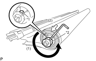
Text in Illustration *1 Circular Hole *2 Hexagonal Part Place a socket wrench on the hexagonal part shown in the illustration and turn the No. 2 sunshade trim assembly 17 times in the direction indicated by the arrow (1) shown in the illustration.
Tech Tips
Torque: 0.23 N*m (2.35 kgf*cm, 2.04 in.*lbf)
-
Insert a 2.5 mm hexagon wrench into the circular hole of the No. 2 sunshade trim assembly as shown in the illustration.
Note
Make sure that the hexagon wrench does not fall out when installing the No. 2 sunshade trim assembly.
-
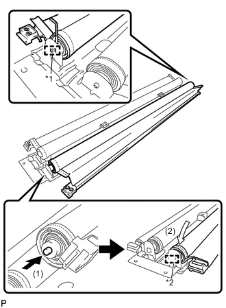
Text in Illustration *1 Guide *2 Pin As shown in the illustration, insert the guide so that the hexagon wrench is upright.
-
Press the pin in the direction indicated by the arrow (1) shown in the illustration.
-
Slide the No. 2 sunshade trim sub-assembly in the direction indicated by the arrow (2) shown in the illustration to install it.
-
Remove the 2.5 mm hexagon wrench.
Tech Tips
Use the same procedure for the other side sunshade trim.
-
-
INSTALL SUNSHADE TRIM SUB-ASSEMBLY
-
Wrap the sunshade cover as shown in the illustration.
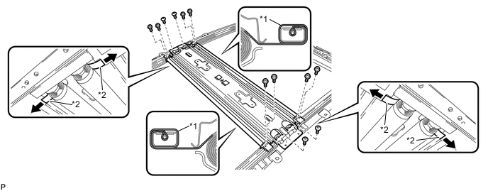
Text in Illustration *1 Sunshade Cover *2 End of Sunshade Cover -
Insert the ends of the sunshade cover to the slide roof rail sub-assembly.
-
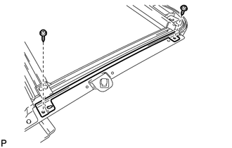
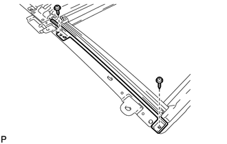
Using a T20 "TORX" socket wrench, install the sunshade trim sub-assembly to the slide roof rail sub-assembly with the 4 "TORX" screws.
- Torque:
- 4.0 N*m { 41 kgf*cm, 35 in.*lbf }
-
Temporary install the 8 screws.
-
Perform a gap check.
-
Check that the clearance between each front sliding roof bracket plate and the sliding roof rail sub-assembly are as specified.
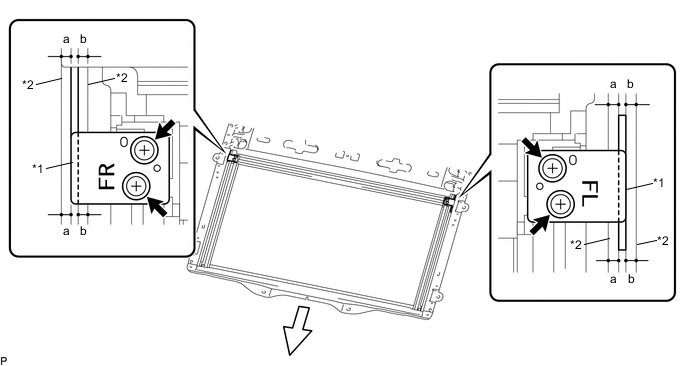
Text in Illustration *1 Sliding Roof Bracket Plate *2 Sliding Roof Rail Sub-assembly 
Front - - Standard The clearance measurements of (a) and (b) shown in the illustration should be the same for both sliding roof bracket plates. Reference Dimension Measurement (a) and (b): 1.5 mm Note
If the clearance measurements are not the same, the sliding roof bracket plate and sliding roof rail sub-assembly may interfere with each other and cause noise.
-
Tighten the 4 screws.
- Torque:
- 2.0 N*m { 20 kgf*cm, 18 in.*lbf }
-
Check that the clearance between each rear sliding roof bracket plate and the sliding roof rail sub-assembly are as specified.
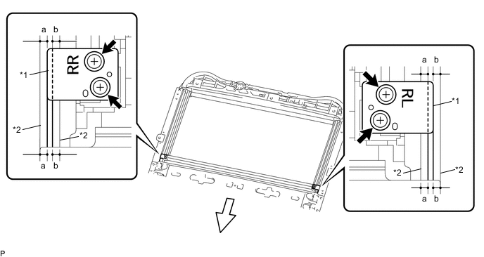
Text in Illustration *1 Sliding Roof Bracket Plate *2 Sliding Roof Rail Sub-assembly Front - - Standard The clearance measurements of (a) and (b) shown in the illustration should be the same for both sliding roof bracket plates. Reference Dimension Measurement (a) and (b): 1.5 mm Note
If the clearance measurements are not the same, the sliding roof bracket plate and sliding roof rail sub-assembly may interfere with each other and cause noise.
-
Tighten the 4 screws.
- Torque:
- 2.0 N*m { 20 kgf*cm, 18 in.*lbf }
-
-
-
INSTALL SLIDING ROOF DRIVE GEAR ASSEMBLY
-
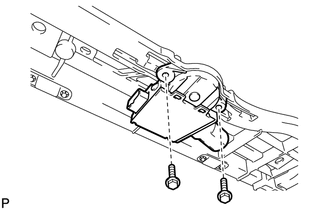
Install the sliding roof drive gear assembly with the 2 bolts.
- Torque:
- 5.4 N*m { 55 kgf*cm, 48 in.*lbf }
-
-
INSTALL CONNECTOR WIRE
-
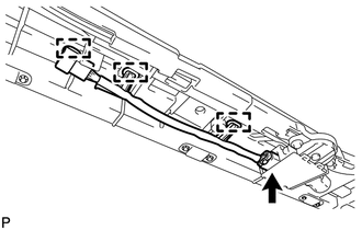
Engage the 3 clamps.
-
Connect the connector to install the connector wire.
-
-
INSTALL NO. 2 SUNSHADE GARNISH LH
-
Install the No. 2 sunshade garnish LH with the 2 screws.
- Torque:
- 2.0 N*m { 20 kgf*cm, 18 in.*lbf }
-
-
INSTALL NO. 2 SUNSHADE GARNISH RH
Tech Tips
Use the same procedure as for the LH side.
-
INSTALL NO. 1 SUNSHADE GARNISH LH
-
Install the No. 1 sunshade garnish LH with the 2 screws.
- Torque:
- 2.0 N*m { 20 kgf*cm, 18 in.*lbf }
-
-
INSTALL NO. 1 SUNSHADE GARNISH RH
Tech Tips
Use the same procedure as for the LH side.