HYBRID BATTERY SYSTEM TERMINALS OF ECU
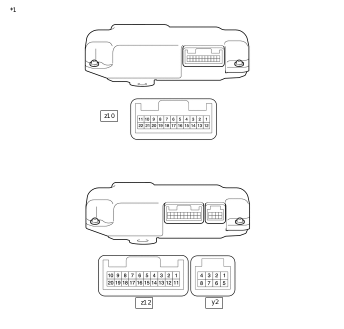
*1 |
Battery Voltage Sensor |
- |
- |
Terminal No. (Symbol) |
Wiring Color |
Terminal Description |
Condition |
Specified Condition |
|---|---|---|---|---|
z12-1 (TC0) - z12-11 (GC0) |
G - G |
Intake air temperature sensor |
HV battery temperature: -40 to 90°C (-40 to 194°F) |
4.8 (-40°C (-40°F)) to 1.0 V (90°C (194°F)) |
z12-2 (TB5) - z12-12 (GB5) |
P - P |
Battery temperature sensor 5 |
HV battery temperature: -40 to 90°C (-40 to 194°F) |
4.8 (-40°C (-40°F)) to 1.0 V (90°C (194°F)) |
z12-3 (TB4) - z12-13 (GB4) |
GR - GR |
Battery temperature sensor 4 |
HV battery temperature: -40 to 90°C (-40 to 194°F) |
4.8 (-40°C (-40°F)) to 1.0 V (90°C (194°F)) |
z12-4 (TB3) - z12-14 (GB3) |
SB - SB |
Battery temperature sensor 3 |
HV battery temperature: -40 to 90°C (-40 to 194°F) |
4.8 (-40°C (-40°F)) to 1.0 V (90°C (194°F)) |
z12-5 (TB2) - z12-15 (GB2) |
L - L |
Battery temperature sensor 2 |
HV battery temperature: -40 to 90°C (-40 to 194°F) |
4.8 (-40°C (-40°F)) to 1.0 V (90°C (194°F)) |
z12-6 (TB1) - z12-16 (GB1) |
W - W |
Battery temperature sensor 1 |
HV battery temperature: -40 to 90°C (-40 to 194°F) |
4.8 (-40°C (-40°F)) to 1.0 V (90°C (194°F)) |
z12-7 (TB0) - z12-17 (GB0) |
R - R |
Battery temperature sensor 0 |
HV battery temperature: -40 to 90°C (-40 to 194°F) |
4.8 (-40°C (-40°F)) to 1.0 V (90°C (194°F)) |
z12-9 (IB) - z12-20 (GIB) |
Y - B |
Current sensor |
Power switch on (READY) |
0.5 to 4.5 V |
z12-10 (VIB) - z12-20 (GIB) |
BR - B |
Power source for battery current sensor |
Power switch on (IG) |
4.5 to 5.5 V |
y2-1 (IGCT) - y2-5 (GND) |
L - W-B |
Control signal |
Power switch on (READY) |
11 to 14 V |
y2-2 (BTH+) - y2-5 (GND) |
R - W-B |
Serial communication |
Power switch on (IG) |
Pulse generation (waveform 1) |
y2-3 (BTH-) - y2-5 (GND) |
G - W-B |
Serial communication |
Power switch on (IG) |
Pulse generation (waveform 2) |
y2-8 (FP0) - y2-5 (GND) |
LG - W-B |
Battery cooling blower No. 1 monitor signal |
Cooling blower stopped |
4.5 to 5.5 V |
Cooling blower activated |
Pulse generation (waveform 3) |
|||
y2-7 (FP1) - y2-5 (GND) |
BR - W-B |
Battery cooling blower No. 2 monitor signal |
Cooling blower stopped |
4.5 to 5.5 V |
Cooling blower activated |
Pulse generation (waveform 4) |
|||
y2-5 (GND) - Body ground |
W-B |
Ground |
Always (continuity check) |
Below 1 Ω |
Oscilloscope waveforms
Tip:Oscilloscope waveform samples are provided here for informational purposes. Noise and fluttering waveforms have been omitted.
-
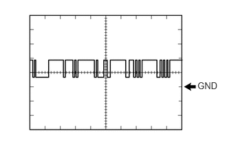
Waveform 1
Item
Content
Terminal
y2-2 (BTH+) - y2-5 (GND)
Equipment Setting
2 V/DIV., 500 μs/DIV.
Condition
Power switch on (IG)
Tip:The waveform will vary depending on the content of the digital communication (digital signal).
-
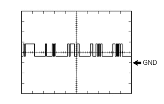
Waveform 2
Item
Content
Terminal
y2-3 (BTH-) - y2-5 (GND)
Equipment Setting
2 V/DIV., 500 μs/DIV.
Condition
Power switch on (IG)
Tip:The waveform will vary depending on the content of the digital communication (digital signal).
-
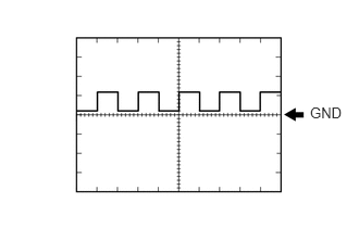
Waveform 3
Item
Content
Terminal
y2-8 (FP0) - y2-5 (GND)
Equipment Setting
5 V/DIV., 1 ms/DIV.
Condition
Battery cooling blower assembly (No. 0) operating (Active Test of cooling fan being performed)
Tip:The frequency of the waveform will vary with the operating speed of the battery cooling blower assembly (No. 0).
-
Waveform 4
Item
Content
Terminal
y2-7 (FP0) - y2-5 (GND)
Equipment Setting
5 V/DIV., 1 ms/DIV.
Condition
Battery cooling blower assembly (No. 1) operating (Active Test of cooling fan being performed)
Tip:The frequency of the waveform will vary with the operating speed of the battery cooling blower assembly (No. 1).
-