FRONT FLOOR AIRBAG SENSOR INSTALLATION
CAUTION / NOTICE / HINT
Tech Tips
-
Use the same procedure for RHD and LHD vehicles.
-
The procedure listed below is for LHD vehicles.
-
Use the same procedure for the RH and LH sides.
-
The procedure listed below is for the LH side.
PROCEDURE
-
INSTALL NO. 2 SIDE AIRBAG SENSOR ASSEMBLY
-
Check that the engine switch is off.
-
Check that the cable is disconnected from the negative (-) battery terminal.
CAUTION:
-
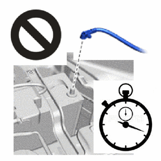
Wait at least 90 seconds after disconnecting the cable from the negative (-) battery terminal to disable the SRS system.
-
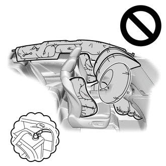
If this procedure is performed without disconnecting the negative (-) battery terminal of the battery, the airbag may deploy even if an impact is applied only to the side airbag sensor assembly LH. Therefore, make sure that the negative (-) battery terminal of the battery is disconnected before performing this procedure.
-
-
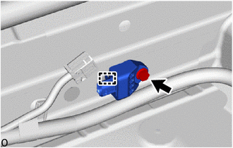
Attach the guide to hold the No. 2 side airbag sensor assembly LH in place.
-
Install the bolt.
- Torque:
- 9.0 N*m { 92 kgf*cm, 80 in.*lbf }
Note
-
If the No. 2 side airbag sensor assembly LH has been dropped, replace it with a new one.
-
When installing the No. 2 side airbag sensor assembly LH, be careful that the SRS wiring does not interfere with or is not pinched between other parts.
-
Tighten the bolt while holding the No. 2 side airbag sensor assembly LH because the No. 2 side airbag sensor assembly LH guide is easily damaged.
-
Check that there is no looseness in the installation parts of the No. 2 side airbag sensor assembly LH.
-
Connect the airbag connector.
Note
When connecting any airbag connector, take care not to damage the airbag wire harness.
-
Before connecting the connector, check that the position of the housing lock is correct as shown in the illustration.
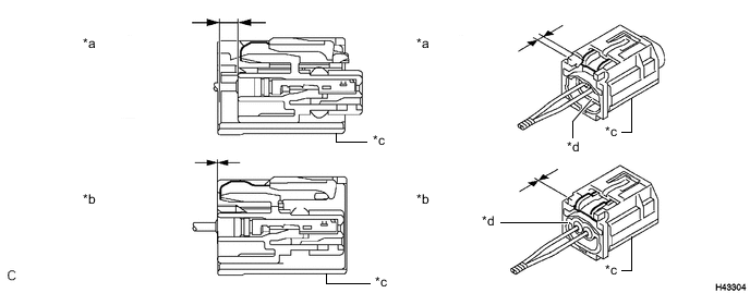
*a Correct *b Incorrect *c CPA *d Housing Lock -
While holding the CPA be sure to engage the connectors until they are locked and check that the CPA is in its original position (when locking, make sure that a click sound can be heard).
Note
Do not push down the upper part of the CPA shown in the illustration when connecting the airbag connector.
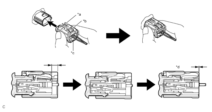
*a CPA Upper Part *b Housing Lock *c CPA *d Connection is Completed
-
-
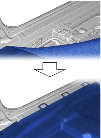
Return the floor carpet to its original position.
-
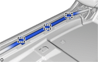
Attach the wire harness clamp.
-
-
INSTALL LOWER CENTER PILLAR GARNISH LH
-
INSTALL REAR DOOR SCUFF PLATE LH
-
INSTALL COWL SIDE TRIM BOARD LH
-
INSTALL NO. 1 INSTRUMENT PANEL UNDER COVER SUB-ASSEMBLY
-
INSTALL INSTRUMENT SIDE PANEL LH
-
INSTALL FRONT DOOR SCUFF PLATE LH
-
INSTALL FRONT SEAT ASSEMBLY LH
-
PERFORM DIAGNOSTIC SYSTEM CHECK
-
CHECK SRS WARNING LIGHT