ECD SYSTEM, Diagnostic DTC:18 (5)
| DTC Code | DTC Name |
|---|---|
| 18 (5) | Spill Control Circuit Malfunction |
DESCRIPTION
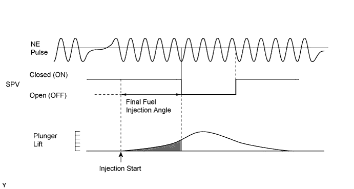
The ECM controls the fuel injection volume by operating the spill control valve. The spill control valve is mounted on the injection pump, and opens or closes the injection pressure releasing port with the solenoid valve in the spill control valve. During injection, valve is closed (ON). The ECM decides the basic fuel injection volume based on the engine rpm and accelerator pedal opening angle, and calculates the final fuel injection angle to add the various corrections on the basic fuel injection volume. The ECM counts the NE pulse to detect the angle from injection starts and operates the spill control valve from ON to OFF (the injection pressure releasing port is open) at the position which watches the final fuel injection angle.
| DTC No. | DTC Detection Condition | Trouble Area |
|---|---|---|
| 18 (5) | Open or short in spill control valve at 500 rpm or more |
|
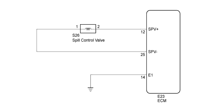
WIRING DIAGRAM
INSPECTION PROCEDURE
PROCEDURE
-
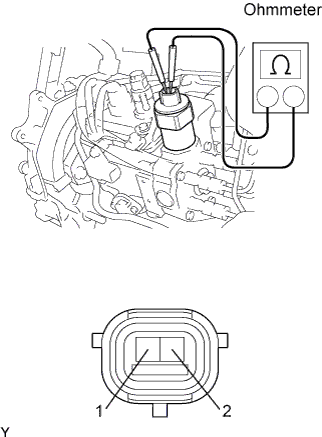
INSPECT SPILL CONTROL VALVE
-
Disconnect the spill control valve connector.
-
Measure the resistance of the spill control valve.
Standard resistance Tester Connection Condition Specified Condition 1 - 2 20°C (68°F) 1 to 2 Ω Tech Tips
The spill control valve is integrated with the injection pump. If the spill control valve needs to be replaced, the entire injection pump must be replaced.
NG 
REPLACE INJECTION PUMP ASSEMBLY
OK 
-
-
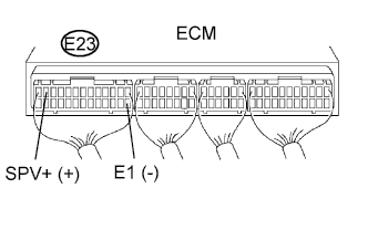
CHECK ECM (SPV+ VOLTAGE)
-
Disconnect the S26 spill control valve connector.
-
Turn the ignition switch ON.
-
Measure the voltage of the ECM connector.
Standard voltage Tester Connection Specified Condition E23-12 (SPV+) - E23-14 (E1) 9 to 14 V
NG
REPLACE ECM
OK
-
-
CHECK ECM (SPV- VOLTAGE)
-
Turn the ignition switch ON.
-
Measure the voltage of the ECM connector.
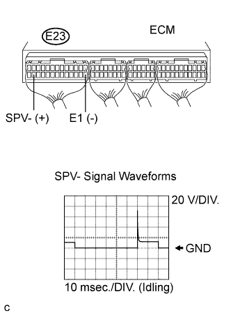
Standard voltage Tester Connection Specified Condition E23-25 (SPV-) - E23-14 (E1) 9 to 14 V -
While idling, measure the waveform with an oscilloscope connected between the specified terminals of ECM connector.
OK Tester Connection Specified Condition SPV- (E23-25) - E1 (E23-14) Correct waveform is as shown
OK
CHECK FOR INTERMITTENT PROBLEMS
NG
-
-
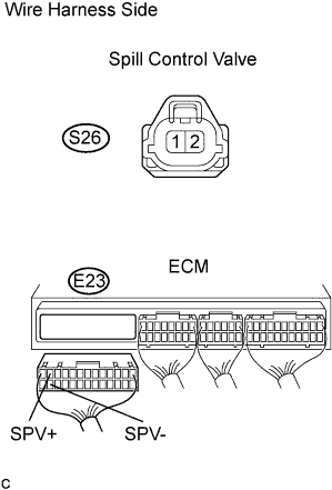
CHECK WIRE HARNESS (ECM - SPILL CONTROL VALVE)
-
Disconnect the S26 spill control valve connector.
-
Disconnect the E23 ECM connector.
-
Measure the resistance of the wire harness side connectors.
Standard resistance Tester Connection Specified Condition S26-2 - E23-12 (SPV+) Below 1 Ω S26-1 - E23-25 (SPV-) Below 1 Ω E23-12 (SPV+) - Body ground 10 kΩ or higher E23-25 (SPV-) - Body ground 10 kΩ or higher
NG
REPAIR OR REPLACE HARNESS AND CONNECTOR
OK 
REPLACE ECM
-