FRONT AXLE HUB (for 2WD) INSTALLATION
Tech Tips
-
Use the same procedures for the RH side and LH side.
-
The procedures listed below are for the LH side.
-
A bolt without a torque specification is shown in the standard bolt chart Click here.
-
INSTALL FRONT AXLE HUB INNER BEARING
-
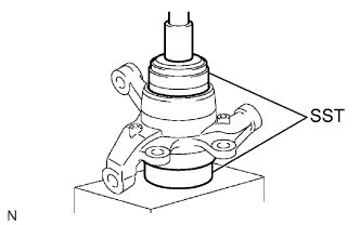
Using SST and a press, press a new bearing into the steering knuckle.
- SST
- 09527-17011
- 09950-60020 ( 09951-00910 )
-
Using snap ring pliers, install a new snap ring.
-
-
INSTALL FRONT AXLE HUB OIL SEAL
-
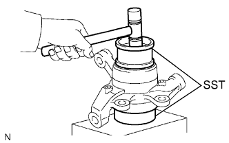
Using SST and a plastic-faced hammer, tap in a new oil seal.
- SST
- 09223-15030
- 09527-17011
-
Apply MP grease to the lip of the oil seal.
-
-
INSTALL AXLE HUB TO STEERING KNUCKLE
-
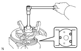
Install the dust cover to the steering knuckle with the 3 bolts.
- Torque:
- 8.0 N*m { 82 kgf*cm, 71 in.*lbf }
-
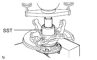
Using SST and a press, press the axle hub into the steering knuckle.
- SST
- 09223-00010
-
-
INSTALL FRONT AXLE HUB NUT AND ABS SPEED SENSOR ROTOR OR SPACER
-
w/ ABS:
Install the ABS speed sensor rotor.
-
w/o ABS:
Install the spacer.
-
Install a new nut to the axle hub.
- Torque:
- 199 N*m { 2,029 kgf*cm, 147 ft.*lbf }
-
Using a chisel and hammer, stake the nut.
Note
Do not scratch the serration of the speed sensor rotor.
-
-
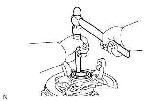
INSTALL KNUCKLE GREASE RETAINER CAP
-
Using a brass bar and hammer, install the knuckle grease retainer cap.
Note
Do not damage the knuckle grease retainer cap.
-
-
INSTALL FRONT AXLE HUB ASSEMBLY
-
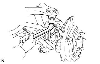
CONNECT FRONT SUSPENSION UPPER ARM ASSEMBLY LH
-
Connect the upper arm with the nut.
- Torque:
- 110 N*m { 1,122 kgf*cm, 81 ft.*lbf }
-
Install a new clip.
Note
If the holes for the clip are not aligned, tighten the nut an additional 60°.
-
-
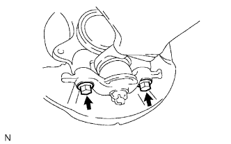
CONNECT FRONT SUSPENSION LOWER ARM ASSEMBLY WITH ATTACHMENT LH
-
Connect the suspension arm with the 2 bolts.
- Torque:
- 160 N*m { 1,632 kgf*cm, 118 ft.*lbf }
-
-
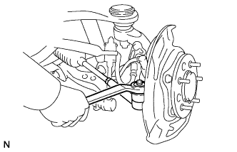
INSTALL TIE ROD END SUB-ASSEMBLY
-
Connect the tie rod end with the nut.
- Torque:
- 49 N*m { 500 kgf*cm, 36 ft.*lbf }
-
Install a new cotter pin.
Note
If the holes for the cotter pin are not aligned, tighten the nut an additional 60°.
-
-
INSTALL FRONT DISC
-
INSTALL FRONT SPEED SENSOR LH
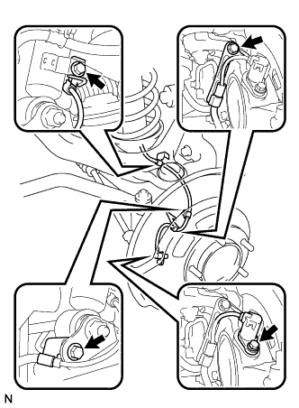
-
Install the speed sensor with the bolt.
- Torque:
- 8.5 N*m { 87 kgf*cm, 75 in.*lbf }
-
Connect the 3 clamps with the 3 bolts.
- Torque:
- 32 N*m { 326 kgf*cm, 24 ft.*lbf }
-
-
INSTALL FRONT DISC BRAKE CYLINDER ASSEMBLY LH
-
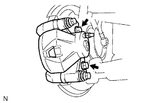
Install the brake cylinder with the 2 bolts.
- Torque:
- 126 N*m { 1,285 kgf*cm, 93 ft.*lbf }
-
Connect the brake hose to the brake cylinder with the union bolt and a new gasket.
- Torque:
- 29 N*m { 296 kgf*cm, 21 ft.*lbf }
-
-
BLEED BRAKE LINE
-
for TSAM Made:
-
for TMT Made :
-
w/ VSC:
-
-
INSTALL FRONT WHEEL
- Torque:
- 152 N*m { 1,550 kgf*cm, 112 ft.*lbf, for steel type }
- 121 N*m { 1,234 kgf*cm, 89 ft.*lbf, for aluminum type }
-
CHECK ABS SPEED SENSOR SIGNAL
-
Check the ABS speed sensor signal Click here.
-