SLIDING ROOF SYSTEM Sliding Roof does not Move by Operating Sliding Roof Control Switch
| DTC Code | DTC Name |
|---|---|
| Sliding Roof does not Move by Operating Sliding Roof Control Switch |
DESCRIPTION
The sliding roof drive gear sub-assembly (sliding roof ECU) receives slide and tilt signals when the sliding roof control switch is operated and drives its built-in motor.
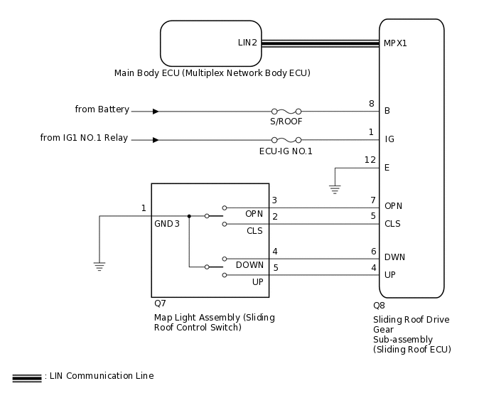
WIRING DIAGRAM
CAUTION / NOTICE / HINT
Inspect the fuses for circuits related to this system before performing the following procedure.
When the sliding roof drive gear sub-assembly (sliding roof ECU) is removed and reinstalled or replaced, it requires initialization.
The sliding roof system uses the LIN communication system. First, confirm that there are no malfunctions in the LIN communication system. Refer to the How to Proceed with Troubleshooting procedure.
Click here
When a sliding roof drive gear sub-assembly (sliding roof ECU) DTC is output, first perform troubleshooting for the sliding roof drive gear sub-assembly (sliding roof ECU) DTC.
PROCEDURE
READ VALUE USING GTS
Connect the GTS to the DLC3.
Turn the ignition switch to ON.
Turn the GTS on.
Enter the following menus: Body Electrical / Sliding Roof / Data List.
Read the Data List according to the display on the GTS.
Body Electrical > Sliding Roof > Data List
Tester Display
Measurement Item
Range
Normal Condition
Diagnostic Note
Open Switch
OPEN switch signal
ON or OFF
ON: OPEN switch pressed
OFF: OPEN switch not pressed
-
Close Switch
CLOSE switch signal
ON or OFF
ON: CLOSE switch pressed
OFF: CLOSE switch not pressed
-
Up Switch
UP switch signal
ON or OFF
ON: UP switch pressed
OFF: UP switch not pressed
-
Down Switch
DOWN switch signal
ON or OFF
ON: DOWN switch pressed
OFF: DOWN switch not pressed
-
Body Electrical > Sliding Roof > Data List
Tester Display
Open Switch
Close Switch
Up Switch
Down Switch
OK
The GTS display changes according to switch operation as shown in the table.
Result
Proceed to
OK
NG
NG INSPECT MAP LIGHT ASSEMBLY (SLIDING ROOF CONTROL SWITCH)Click here
CHECK HARNESS AND CONNECTOR (SLIDING ROOF ECU - BATTERY AND BODY GROUND)
-
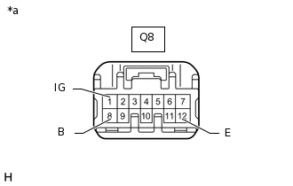
*a
Front view of wire harness connector
(to Sliding Roof Drive Gear Sub-assembly [Sliding Roof ECU])
Disconnect the sliding roof drive gear sub-assembly (sliding roof ECU) connector.
Measure the voltage according to the value(s) in the table below.
Standard Voltage
Tester Connection
Condition
Specified Condition
Q8-8 (B) - Body ground
Always
11 to 14 V
Q8-1 (IG) - Body ground
Ignition switch ON
11 to 14 V
Q8-1 (IG) - Body ground
Ignition switch off
Below 1 V
Measure the resistance according to the value(s) in the table below.
Standard Resistance
Tester Connection
Condition
Specified Condition
Q8-12 (E) - Body ground
Always
Below 1 Ω
Result
Proceed to
OK
NG
NG REPAIR OR REPLACE HARNESS OR CONNECTOR
-
INSPECT MAP LIGHT ASSEMBLY (SLIDING ROOF CONTROL SWITCH)
-
Remove the map light assembly (sliding roof control switch).
Measure the resistance according to the value(s) in the table below.
Standard Resistance
Tester Connection
Switch Condition
Specified Condition
5 (UP) - 1 (GND3)
UP switch is pressed
Below 1 Ω
5 (UP) - 1 (GND3)
UP switch is not pressed
10 kΩ or higher
4 (DOWN) - 1 (GND3)
DOWN switch is pressed
Below 1 Ω
4 (DOWN) - 1 (GND3)
DOWN switch is not pressed
10 kΩ or higher
3 (OPN) - 1 (GND3)
OPEN switch is pressed
Below 1 Ω
3 (OPN) - 1 (GND3)
OPEN switch is not pressed
10 kΩ or higher
2 (CLS) - 1 (GND3)
CLOSE switch is pressed
Below 1 Ω
2 (CLS) - 1 (GND3)
CLOSE switch is not pressed
10 kΩ or higher
Result
Proceed to
OK
NG
-
CHECK HARNESS AND CONNECTOR (SLIDING ROOF ECU - SLIDING ROOF CONTROL SWITCH AND BODY GROUND)
Disconnect the Q7 map light assembly (sliding roof control switch) connector.
Disconnect the Q8 sliding roof drive gear sub-assembly (sliding roof ECU) connector.
Measure the resistance according to the value(s) in the table below.
Standard Resistance
Tester Connection
Condition
Specified Condition
Q8-5 (CLS) - Q7-2 (CLS)
Always
Below 1 Ω
Q8-5 (CLS) - Body ground
Always
10 kΩ or higher
Q8-7 (OPN) - Q7-3 (OPN)
Always
Below 1 Ω
Q8-7 (OPN) - Body ground
Always
10 kΩ or higher
Q8-6 (DWN) - Q7-4 (DOWN)
Always
Below 1 Ω
Q8-6 (DWN) - Body ground
Always
10 kΩ or higher
Q8-4 (UP) - Q7-5 (UP)
Always
Below 1 Ω
Q8-4 (UP) - Body ground
Always
10 kΩ or higher
Q7-1 (GND3) - Body ground
Always
Below 1 Ω
Q8-12 (E) - Body ground
Always
Below 1 Ω
Result
Proceed to
OK
NG
NG REPAIR OR REPLACE HARNESS OR CONNECTOR