CAN COMMUNICATION SYSTEM(w/ Central Gateway ECU) SYSTEM DIAGRAM
-
OVERALL CAN BUS DIAGRAM (for LHD)
-
The CAN communication system is composed of 6 buses.
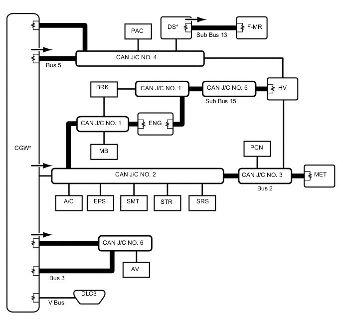

CAN Main Bus Line 
Terminating Resistor 
CAN Branch Line * Gateway Function Equipped ECU 
Bus Monitored Direction - - Connected to Code ECU/Sensor Name CAN DTC Storage Note - CGW Central Gateway ECU (Network Gateway ECU) - - V Bus DLC3 DLC3 - - Bus 2 ENG ECM Available - BRK Brake Booster with Master Cylinder Assembly (Skid Control ECU) Available - MB Main Body ECU (Multiplex Network Body ECU) Available Connected to LIN communication system A/C Air Conditioning Amplifier Assembly Available Connected to LIN communication system EPS Power Steering ECU Assembly Available - SMT Certification ECU (Smart Key ECU Assembly) Available Connected to LIN communication system STR Spiral Cable with Sensor Sub-assembly (Steering Angle Sensor) - - SRS Airbag ECU Assembly - - PCN Transmission Control ECU Assembly Available Connected to LIN communication system MET Combination Meter Sub-assembly Available - HV Hybrid Vehicle Control ECU Available - CAN J/C No. 1 No. 1 CAN Junction Connector - - CAN J/C No. 2 No. 2 CAN Junction Connector - - CAN J/C No. 3 No. 3 CAN Junction Connector - - Bus 3 AV Radio and Display Receiver Assembly Available for Radio and Display Type CAN J/C No. 6 No. 6 CAN Junction Connector - - Bus 5 HV Hybrid Vehicle Control ECU Available - DS Driving Support ECU Assembly Available w/ Pre-crash Safety System PAC Parking Assist ECU Available w/ Intelligent Parking Assist System CAN J/C No. 4 No. 4 CAN Junction Connector - - Sub Bus 13 DS Driving Support ECU Assembly Available w/ Pre-crash Safety System F-MR Millimeter Wave Radar Sensor Assembly - w/ Pre-crash Safety System Sub Bus 15 HV Hybrid Vehicle Control ECU Available - ENG ECM Available - BRK Brake Booster with Master Cylinder Assembly (Skid Control ECU) Available - CAN J/C No. 1 No. 1 CAN Junction Connector - - CAN J/C No. 5 No. 5 CAN Junction Connector - -
-
-
OVERALL CAN BUS DIAGRAM (for RHD)
-
The CAN communication system is composed of 6 buses.
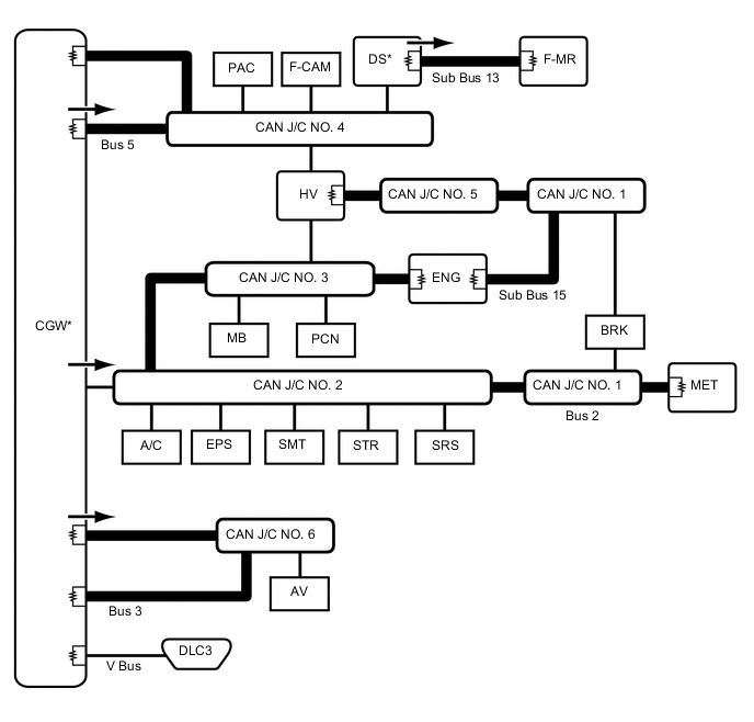
CAN Main Bus Line Terminating Resistor CAN Branch Line * Gateway Function Equipped ECU Bus Monitored Direction - - Connected to Code ECU/Sensor Name CAN DTC Storage Note - CGW Central Gateway ECU (Network Gateway ECU) - - V Bus DLC3 DLC3 - - Bus 2 ENG ECM Available - BRK Brake Booster with Master Cylinder Assembly (Skid Control ECU) Available - MB Main Body ECU (Multiplex Network Body ECU) Available Connected to LIN communication system A/C Air Conditioning Amplifier Assembly Available Connected to LIN communication system EPS Power Steering ECU Assembly Available - SMT Certification ECU (Smart Key ECU Assembly) Available Connected to LIN communication system STR Spiral Cable with Sensor Sub-assembly (Steering Angle Sensor) - - SRS Airbag ECU Assembly - - PCN Transmission Control ECU Assembly Available Connected to LIN communication system MET Combination Meter Sub-assembly Available - HV Hybrid Vehicle Control ECU Available - CAN J/C No. 1 No. 1 CAN Junction Connector - - CAN J/C No. 2 No. 2 CAN Junction Connector - - CAN J/C No. 3 No. 3 CAN Junction Connector - - Bus 3 AV Radio and Display Receiver Assembly Available for Radio and Display Type Navigation Receiver Assembly Available for Navigation Receiver Type CAN J/C No. 6 No. 6 CAN Junction Connector - - Bus 5 HV Hybrid Vehicle Control ECU Available - F-CAM Lane Departure Warning Camera Available w/ Lane Departure Alert System DS Driving Support ECU Assembly Available w/ Pre-crash Safety System PAC Parking Assist ECU Available w/ Intelligent Parking Assist System CAN J/C No. 4 No. 4 CAN Junction Connector - - Sub Bus 13 DS Driving Support ECU Assembly Available w/ Pre-crash Safety System F-MR Millimeter Wave Radar Sensor Assembly - w/ Pre-crash Safety System Sub Bus 15 HV Hybrid Vehicle Control ECU Available - ENG ECM Available - BRK Brake Booster with Master Cylinder Assembly (Skid Control ECU) Available - CAN J/C No. 1 No. 1 CAN Junction Connector - - CAN J/C No. 5 No. 5 CAN Junction Connector - -
-