EXHAUST MANIFOLD W/ TURBOCHARGER REMOVAL
CAUTION / NOTICE / HINT
The necessary procedures (adjustment, calibration, initialization, or registration) that must be performed after parts are removed, installed, or replaced during the turbocharger sub-assembly removal/installation are shown below.
| Replacement Part or Procedure | Necessary Procedures | Effects/Inoperative when not Performed | Link |
|---|---|---|---|
|
Perform initialization | - |
CAUTION:
-
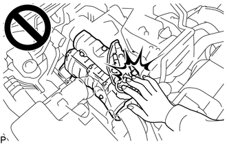
To prevent burns, do not touch the engine, exhaust manifold or other high temperature components while the engine is hot.
-
To prevent burns, do not touch the engine, exhaust pipe or other high temperature components while the engine is hot.
PROCEDURE
-
REMOVE EXHAUST MANIFOLD CONVERTER SUB-ASSEMBLY (w/ EGR Cooler)
-
w/ DPF:
-
w/o DPF:
-
-
REMOVE NO. 1 EXHAUST MANIFOLD HEAT INSULATOR (w/o EGR Cooler)
-
REMOVE NO. 1 TURBO INSULATOR (w/o EGR Cooler)
-
REMOVE NO. 2 EXHAUST PIPE SUPPORT STAY (w/o EGR Cooler)
-
REMOVE EXHAUST PIPE SUPPORT STAY (w/o EGR Cooler)
-
REMOVE TURBINE OUTLET ELBOW (w/o EGR Cooler)
-
REMOVE NO. 1 ENGINE UNDER COVER ASSEMBLY
-
DRAIN ENGINE COOLANT
-
DRAIN ENGINE OIL
-
REMOVE NO. 1 AIR HOSE
-
REMOVE NO. 4 AIR HOSE
-
REMOVE NO. 2 AIR TUBE
-
REMOVE NO. 1 RADIATOR HOSE
-
DISCONNECT VANE PUMP OIL RESERVOIR ASSEMBLY
-
REMOVE NO. 1 OIL RESERVOIR BRACKET
-
REMOVE RADIATOR RESERVOIR
-
REMOVE FAN SHROUD
-
REMOVE AIR CLEANER CAP SUB-ASSEMBLY WITH AIR CLEANER HOSE
-
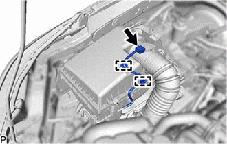
Disconnect the mass air flow meter sub-assembly connector and detach the 2 harness clamps.
-
Detach the 4 clips.
-
Loosen the hose clamp and remove the air cleaner cap sub-assembly with air cleaner hose.
-
-
REMOVE AIR CLEANER FILTER ELEMENT SUB-ASSEMBLY
-
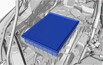
Remove the air cleaner element sub-assembly from the air cleaner case.
-
-
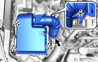
REMOVE AIR CLEANER CASE SUB-ASSEMBLY
-
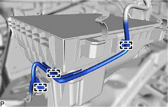
Disconnect the 3 wire harness clamps.
-
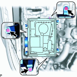
Remove the 3 bolts and air cleaner case sub-assembly.
-
-
REMOVE WATER HOSE SUB-ASSEMBLY (w/ Viscous Heater)
-
REMOVE VISCOUS HEATER WITH MAGNET CLUTCH ASSEMBLY (w/ Viscous Heater)
-
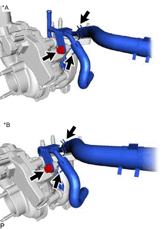
REMOVE NO. 3 WATER BY-PASS PIPE
-
for Cold Specification Vehicles:
Slide the 2 clips and remove the water hose from the compressor inlet elbow and No. 3 water by-pass pipe.
-
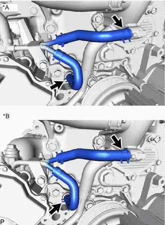
*A for Cold Specification Vehicles *B except Cold Specification Vehicles Slide the 2 clips and disconnect the 2 water hoses from the oil cooler assembly and No. 2 water by-pass pipe.
-
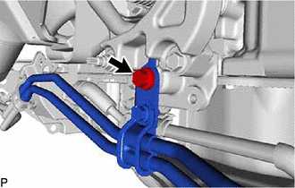
Remove the bolt and No. 3 water by-pass pipe.
-
-
REMOVE PCV PIPE (for Cold Area Specification Vehicles)
-
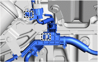
Slide the 2 clips and disconnect the No. 20 water by-pass hose from the compressor inlet elbow and No. 3 water by-pass pipe.
-
Slide the clip and disconnect the No. 19 water by-pass hose from the compressor inlet elbow.
-
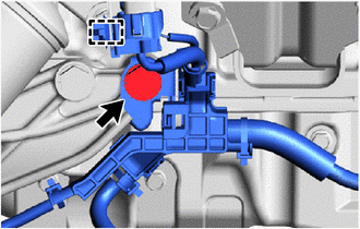
Remove the bolt and disconnect the PCV pipe from the compression outlet elbow.
-
Slide the 2 clips and remove the PCV pipe.
-
-
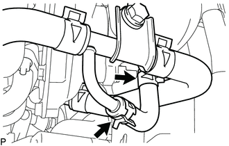
REMOVE PCV HOSE (except Cold Area Specification Vehicles)
-
Slide the 2 clips.
-
Slide the 2 clips, detach the clamp and remove the PCV hose.
-
-
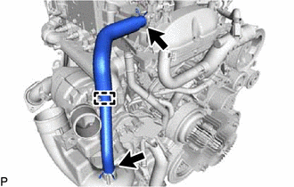
REMOVE NO. 1 WATER BY-PASS PIPE
-
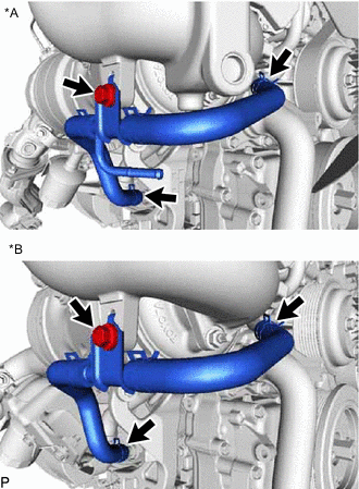
DISCONNECT TURBO WATER HOSE
-
*A for Cold Specification Vehicles *B except Cold Specification Vehicles Slide the 2 clips and disconnect the No. 1 turbo water hose and No. 2 turbo water hose from the water outlet sub-assembly and water pump assembly.
-
-
DISCONNECT BRACKET OIL COOLER TUBE BRACKET AND WIRE HARNESS CLAMP BRACKET (for Automatic Transmission)
-
Remove the bolt and disconnect the oil cooler tube bracket.
-
w/ DPF:
Detach the 2 clamps and disconnect the wire harness.
-

w/o DPF:
Remove the bolt and disconnect the wire harness.
-
-
DISCONNECT WIRE HARNESS CLAMP BRACKET (for Manual Transmission)
-
w/ DPF:
Remove the bolt, detach the clamp and disconnect the wire harness.
-
w/o DPF:
Remove the bolt and disconnect the wire harness.
-
-
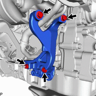
REMOVE NO. 1 VISCOUS HEATER BRACKET SUB-ASSEMBLY (for Cold Area Specification Vehicles)
-
Remove the bolt, detach the clamp and disconnect the wire harness.
-
Remove the 4 bolts and the No. 1 viscous heater bracket sub-assembly.
-
-
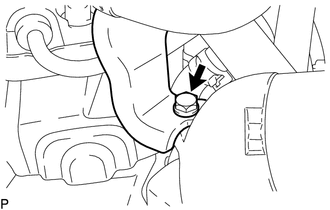
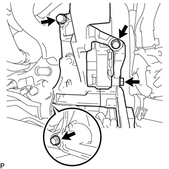
REMOVE TURBOCHARGER STAY
-
Remove the 3 bolts, nut and the turbocharger stay.
-
-
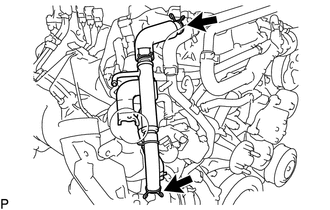
REMOVE TURBO OIL OUTLET PIPE
-
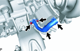
Slide the 2 clips and disconnect the turbo oil outlet hose from the turbo oil outlet pipe.
-
Remove the 2 bolts and turbo oil outlet pipe and gasket.
-
-
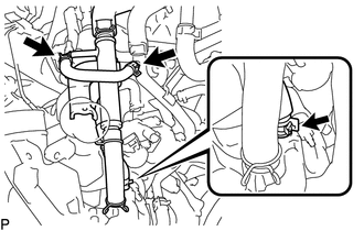
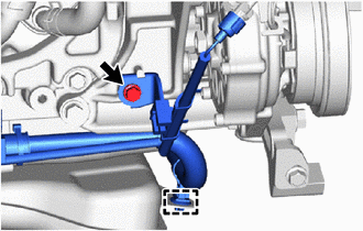
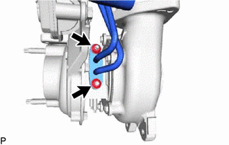
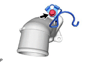
REMOVE TURBO OIL INLET PIPE SUB-ASSEMBLY
-
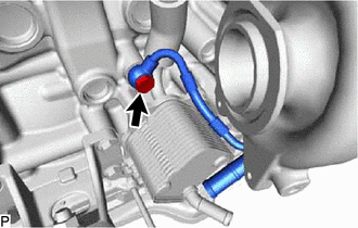
Remove the union bolt and gasket.
-
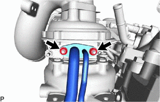
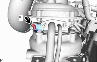
Remove the 2 nuts and the turbo oil inlet pipe sub-assembly.
Note
Do not loosen the nut labeled A.
-
Remove the gasket.
-
-
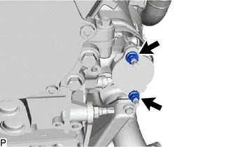
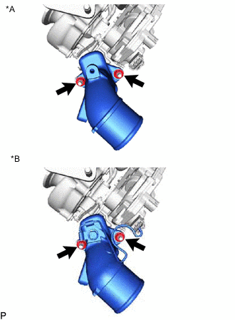
REMOVE TURBOCHARGER SUB-ASSEMBLY
-
*A w/ DPF *B w/o DPF Remove the 3 nuts and turbocharger sub-assembly.
-
Remove the gasket from the exhaust manifold.
-
-
REMOVE NO. 1 EGR PIPE SUB-ASSEMBLY (w/ EGR System)
-
REMOVE EGR HOLE COVER PLATE (w/o EGR System)
-
Remove the 2 nuts, EGR hole cover plate and gasket.
-
Using an E8 "TORX" socket wrench, remove the 2 stud bolts shown in the illustration.
-
-
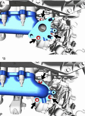
REMOVE EXHAUST MANIFOLD
-
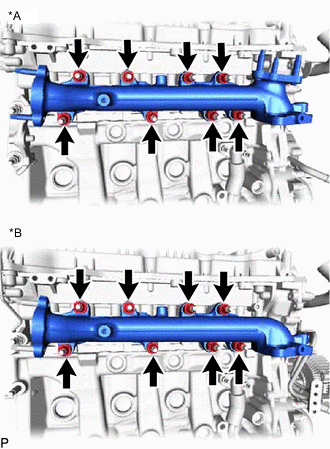
*A w/ DPF *B w/o DPF Remove the 8 nuts, 8 plate washers, 8 collars and exhaust manifold.
-
Remove the gasket.
-
-
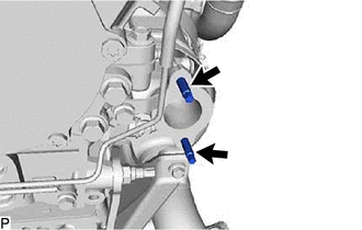
REMOVE NO. 1 TURBO WATER PIPE SUB-ASSEMBLY
-
*A w/ DPF *B w/o DPF Slide the 2 hose clips and disconnect the No. 1 turbo water hose and No. 2 turbo water hose from the turbo water pipe sub-assembly.
-
Remove the bolt.
-
Remove the 2 nuts, turbo water pipe sub-assembly and gasket.
-
-
REMOVE COMPRESSOR INLET ELBOW
-
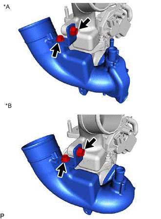
*A for Cold Specification Vehicles *B except Cold Specification Vehicles Remove the 2 bolts and compressor inlet elbow stay.
-
*A for Cold Specification Vehicles *B except Cold Specification Vehicles Remove the 2 nuts and compressor inlet elbow from turbocharger sub-assembly.
-
*A for Cold Specification Vehicles *B except Cold Specification Vehicles Using an E8 "TORX" socket wrench, remove the stud bolt shown in the illustration together with the compressor inlet elbow and gasket.
-
-
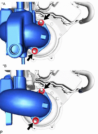
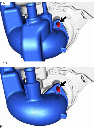
REMOVE COMPRESSOR OUTLET ELBOW
-
*A for Cold Specification Vehicles *B except Cold Specification Vehicles Remove the 2 nuts and compressor outlet elbow.
-
Remove the gasket.
-
except Cold Specification Vehicle:
Remove the bolt and hose clamp.
-
-
REMOVE STUD BOLT
Note
If a stud bolt is deformed or its threads are damaged, replace it.
-
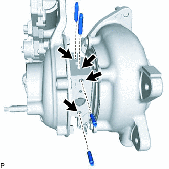
Using an E5 "TORX" socket wrench, remove the 4 stud bolts shown in the illustration.
-
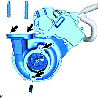
Using an E8 "TORX" socket wrench, remove the 4 stud bolts shown in the illustration.
-
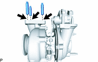
Using an E10 "TORX" socket wrench, remove the 3 stud bolts shown in the illustration.
-