CLUTCH UNIT(for R151) INSPECTION

PROCEDURE
-
INSPECT CLUTCH DISC ASSEMBLY
-
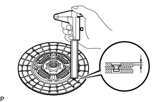
Using a vernier caliper, measure the rivet head depth.
Minimum rivet head depth 0.3 mm (0.0118 in.) If the depth is less than the minimum, replace the clutch disc assembly.
-
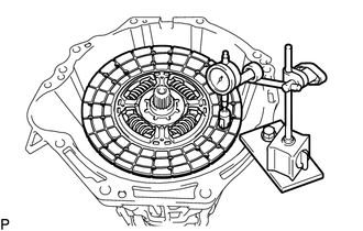
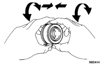
Using a dial indicator, check the disc runout.
Maximum runout 0.8 mm (0.0314 in.) Note
Be sure to measure on the correct side of the clutch disc.
If the runout is more than the maximum, replace the clutch disc assembly.
-
-
INSPECT CLUTCH COVER ASSEMBLY
-
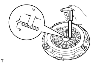
*a Width *b Depth Using a vernier caliper, measure the depth and width of the worn areas of the diaphragm spring.
Maximum width 6.0 mm (0.236 in.) Maximum depth 0.35 mm (0.0137 in.) If the depth or width is more than the maximum, replace the clutch cover assembly.
-
-
INSPECT FLYWHEEL SUB-ASSEMBLY
-
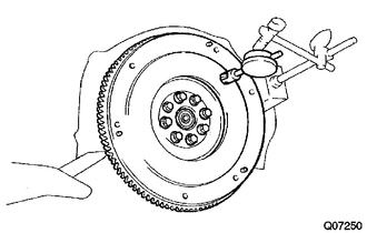
Using a dial indicator, measure the flywheel runout.
Maximum runout 0.1 mm (0.00393 in.) If the runout is more than the maximum, replace the flywheel sub-assembly.
-
-
INSPECT CLUTCH RELEASE BEARING ASSEMBLY
-
Turn the bearing by hand while applying force in the axial direction and check that the bearing rotates smoothly.
If the bearing sticks or a considerable amount of resistance is felt, replace the release bearing.
Tech Tips
The bearing is permanently lubricated and requires no cleaning or lubrication.
-
-
INSPECT INPUT SHAFT FRONT BEARING
-
Turn the bearing by hand while applying rotational force and check that the bearing rotates smoothly.
If the bearing sticks or a considerable amount of resistance is felt, replace the input shaft front bearing.
Tech Tips
The bearing is permanently lubricated and requires no cleaning or lubrication.
-
-
REPLACE INPUT SHAFT FRONT BEARING
-
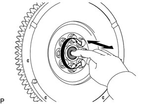
Remove any 2 diametrically opposite bolts.
-
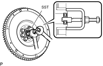
Using SST, remove the input shaft front bearing.
- SST
- 09303-35011
-
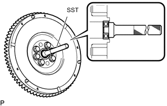
Using SST and a hammer, tap in a new input shaft front bearing.
- SST
- 09304-12012
Tech Tips
After installing the bearing to the crankshaft, make sure that it rotates smoothly.
-
for TR Engine:
-
Install the new 2 bolts.
- Torque:
- 26.5 N*m { 270 kgf*cm, 20 ft.*lbf }
Tech Tips
The mounting bolts are tightened in 2 progressive steps.
-
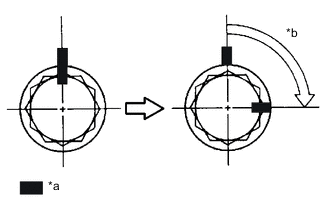
*a Paint Mark *b 90° Mark the mounting bolts with paint.
-
Retighten the mounting bolts by 90°.
-
Check that the paint marks are now at a 90° angle to the original marked position.
-
-
for GD and KD Engine:
-
Install the new 2 bolts.
- Torque:
- 178 N*m { 1815 kgf*cm, 131 ft.*lbf }
-
-