WIRELESS DOOR LOCK CONTROL SYSTEM(w/ Entry and Start System), Diagnostic DTC:B1242
| DTC Code | DTC Name |
|---|---|
| B1242 | Wireless Door Lock Tuner Circuit Malfunction |
DESCRIPTION
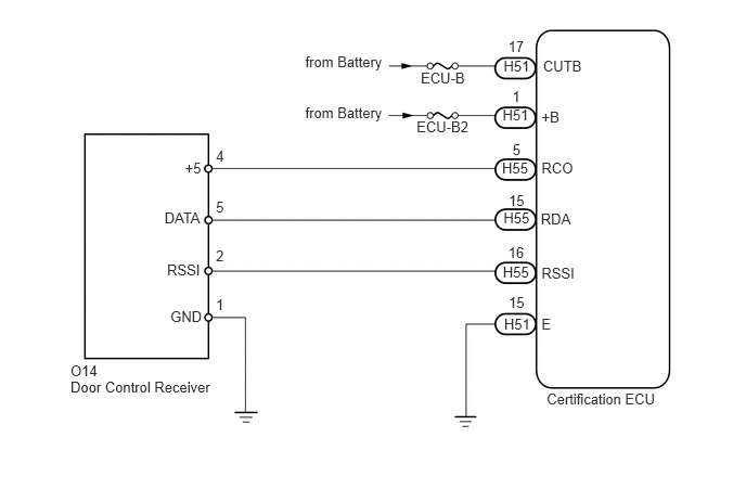
The door lock receiver is used to receive electrical waves relating to the entry functions of the entry and start system (for Entry Function). The certification ECU decodes the requested entry and start system (for Entry Function) operation by identifying a key code based on the electric waves received via the door control receiver. The door control receiver receives a signal from the door control transmitter and sends signals to the main body ECU through the certification ECU. The certification ECU then sends a command, according to the requested operation, to each ECU (ex.: if a door lock operation is requested, the certification ECU sends a door lock command to the main body ECU).
This DTC is stored when one of the following occurs: 1) a short from RDA or RSSI to ground between the certification ECU and the door control receiver, or 2) a short from RDA or RSSI to ground when RCO output (5 V) from the ECU is off.
When replacing or inspecting the door control receiver and wire harness, do not change the position or length of the wire harness. If the wire harness is too close to the door control receiver, entry and wireless function performance may be affected.
Before performing the inspection, check that there are no problems related to the CAN communication system.
When using the intelligent tester with the engine switch off to troubleshoot:
Connect the intelligent tester to the vehicle, and turn the front door courtesy light switch LH*1 or front door courtesy light switch RH*2 on and off at 1.5 second intervals until communication between the intelligent tester and vehicle begins.
*1: for LHD
*2: for RHD
DTC Code |
DTC Detection Condition |
Trouble Area |
|---|---|---|
B1242 |
One of the following conditions is met:
|
|
WIRING DIAGRAM
CAUTION / NOTICE / HINT
Inspect the fuses for circuits related to this system before performing the following inspection procedure.
PROCEDURE
CHECK HARNESS AND CONNECTOR (CERTIFICATION ECU - DOOR CONTROL RECEIVER AND BODY GROUND)
Disconnect the H51 and H55 ECU connectors.
Disconnect the O14 receiver connector.
Measure the resistance according to the value(s) in the table below.
Standard Resistance
Tester Connection
Condition
Specified Condition
H55-16 (RSSI) - O14-2 (RSSI)
Always
Below 1 Ω
H55-15 (RDA) - O14-5 (DATA)
Always
Below 1 Ω
H55-5 (RCO) - O14-4 (+5)
Always
Below 1 Ω
H51-15 (E) - Body ground
Always
Below 1 Ω
O14-1 (GND) - Body ground
Always
Below 1 Ω
H55-16 (RSSI) or O14-2 (RSSI) - Body ground
Always
10 kΩ or higher
H55-15 (RDA) or O14-5 (DATA) - Body ground
Always
10 kΩ or higher
H55-5 (RCO) or O14-4 (+5) - Body ground
Always
10 kΩ or higher
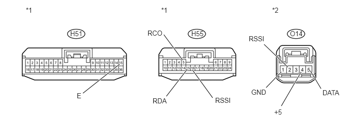
Table 1. Text in Illustration *1
Front view of wire harness connector
(to Certification ECU)
*2
Front view of wire harness connector
(to Door Control Receiver)
REPAIR OR REPLACE HARNESS OR CONNECTOR
CHECK CERTIFICATION ECU
Measure the voltage according to the value(s) in the table below.
Standard Voltage
Tester Connection
Switch Condition
Specified Condition
H55-5 (RCO) - H51-15 (E)
Engine switch off, all doors closed and transmitter switch not pressed → pressed
Below 1 V → 4.5 to 5.5 V
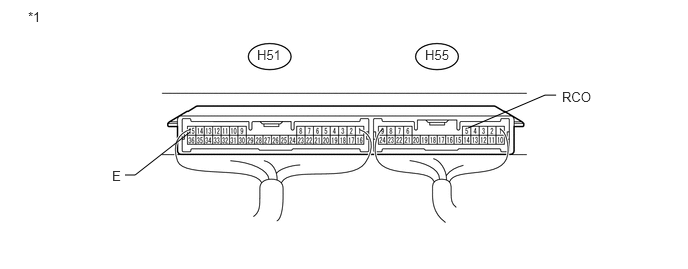
Table 2. Text in Illustration *1
Component with harness connected
(Certification ECU)
-
-
REPLACE CERTIFICATION ECU
REPLACE DOOR CONTROL RECEIVER
Temporarily replace the door control receiver with a new or normally functioning one (Click here).
CLEAR DTC
Clear the DTCs (Click here).
CHECK FOR DTC
Check for DTCs (Click here).
OK
DTC B1242 is not output.
END (DOOR CONTROL RECEIVER IS DEFECTIVE)
REPLACE CERTIFICATION ECU