ECD SYSTEM, Diagnostic DTC:51
| DTC Code | DTC Name |
|---|---|
| 51 | Stop Light Switch Circuit Malfunction |
DESCRIPTION
In this system, the signal of the stop light switch is used to judge whether the stop light system is abnormal or not.
The stop light switch has a duplex system (signals STP and ST1-) to memorize the abnormality when the signals of depressing and releasing the brake pedal are detected simultaneously.
Tech Tips
The normal condition is shown in the table below.
| Signal | Brake pedal released | In transition | Brake pedal depressed |
|---|---|---|---|
| STP | OFF | ON | ON |
| ST1- | ON | ON | OFF |
| DTC No. | DTC Detection Condition | Trouble Area |
|---|---|---|
| 51 | When STP (without depressing the brake pedal) and ST1- (with the brake pedal depressed) signals continue for longer than 0.5 seconds with the ignition switch ON |
|
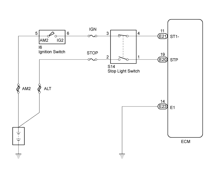
WIRING DIAGRAM
INSPECTION PROCEDURE
Tech Tips
Read freeze frame data using the intelligent tester. The ECM records vehicle and driving condition information as freeze frame data the moment a DTC is stored. When troubleshooting, freeze frame data can be helpful in determining whether the vehicle was running or stopped, whether the engine was warmed up or not, whether the air-fuel ratio was lean or rich, as well as other data recorded at the time of a malfunction.
When using intelligent tester:
PROCEDURE
-
READ VALUE USING INTELLIGENT TESTER (STOP LIGHT SWITCH)
-
Connect the intelligent tester to the DLC3.
-
Turn the ignition switch ON.
-
Enter the following menus: Powertrain / Engine and ECT / Data List / Stop Light SW.
OK Brake Pedal Display Depressed Stop Light SW ON Repressed Stop Light SW OFF
OK 
CHECK FOR INTERMITTENT PROBLEMS
NG 
-
-
CHECK ECM (STP, ST1- VOLTAGE)
-
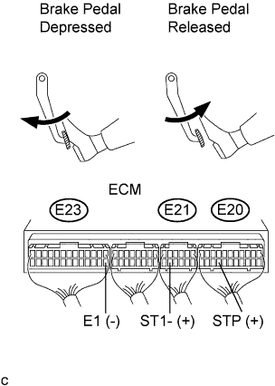
Turn the ignition switch ON.
-
Measure the voltage of the ECM connector.
Standard voltage Brake pedal is depressed Tester Connection Specified Condition E20-19 (STP) - E23-14 (E1) 9 to 14 V E21-11 (ST1-) - E23-14 (E1) Below 1.5 V Standard voltage Brake pedal is released Tester Connection Specified Condition E20-19 (STP) - E23-14 (E1) Below 1.5 V E21-11 (ST1-) - E23-14 (E1) 9 to 14 V
OK
REPLACE ECM
NG
-
-
INSPECT STOP LIGHT SWITCH
-
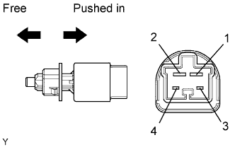
Disconnect the stop light switch connector.
-
Measure the resistance of the sensor.
Standard resistance Tester Connection Switch Position Specified Condition 3 - 4 Switch pin free Below 1 Ω 3 - 4 Switch pin pushed in 10 kΩ or higher 1 - 2 Switch pin free 10 kΩ or higher 1 - 2 Switch pin pushed in Below 1 Ω
NG
REPLACE STOP LIGHT SWITCH
OK
-
-
CHECK WIRE HARNESS (ECM - STOP LIGHT SWITCH)
-
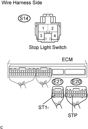
Disconnect the S14 stop light switch connector.
-
Disconnect the E20 and E21 ECM connectors.
-
Measure the resistance of the wire harness side connectors.
Standard resistance Tester Connection Specified Condition S14-1 - E20-19 (STP) Below 1 Ω S14-4 - E21-11 (ST1-) Below 1 Ω E20-19 (STP) - Body ground 10 kΩ or higher E21-11 (ST1-) - Body ground 10 kΩ or higher
NG
REPAIR OR REPLACE HARNESS AND CONNECTOR
OK 
REPAIR OR REPLACE POWER SOURCE CIRCUIT
-
When not using intelligent tester:
PROCEDURE
-
CHECK STOP LIGHT (OPERATION)
-
Check if the stop lights go on and off normally when the brake pedal is depressed and released.
OK The stop lights go on and off normally.
NG
REPAIR STOP LIGHT SWITCH CIRCUIT
OK
-
-
CHECK ECM (STP, ST1- VOLTAGE)
-
Turn the ignition switch ON.
-
Measure the voltage of the ECM connector.
Standard voltage Brake pedal is depressed Tester Connection Specified Condition E20-19 (STP) - E23-14 (E1) 9 to 14 V E21-11 (ST1-) - E23-14 (E1) Below 1.5 V Standard voltage Brake pedal is released Tester Connection Specified Condition E20-19 (STP) - E23-14 (E1) Below 1.5 V E21-11 (ST1-) - E23-14 (E1) 9 to 14 V
OK
REPLACE ECM
NG
-
-
INSPECT STOP LIGHT SWITCH
-
Disconnect the stop light switch connector.
-
Measure the resistance of the sensor.
Standard resistance Tester Connection Switch Position Specified Condition 3 - 4 Switch pin free Below 1 Ω 3 - 4 Switch pin pushed in 10 kΩ or higher 1 - 2 Switch pin free 10 kΩ or higher 1 - 2 Switch pin pushed in Below 1 Ω
NG
REPLACE STOP LIGHT SWITCH
OK
-
-
CHECK WIRE HARNESS (ECM - STOP LIGHT SWITCH)
-
Disconnect the S14 stop light switch connector.
-
Disconnect the E20 and E21 ECM connectors.
-
Measure the resistance of the wire harness side connectors.
Standard resistance Tester Connection Specified Condition S14-1 - E20-19 (STP) Below 1 Ω S14-4 - E21-11 (ST1-) Below 1 Ω E20-19 (STP) - Body ground 10 kΩ or higher E21-11 (ST1-) - Body ground 10 kΩ or higher
NG
REPAIR OR REPLACE HARNESS AND CONNECTOR
OK
REPAIR OR REPLACE POWER SOURCE CIRCUIT
-