DYNAMIC RADAR CRUISE CONTROL SYSTEM TERMINALS OF ECU
-
CHECK DRIVING SUPPORT ECU ASSEMBLY

Note
Do not apply excessive force to the connector. If a force of 10 kg or more is applied, the connector may be broken.
Tester Connection Wiring Color Terminal Description Condition Specified Condition G68-7 (B) - G68-28 (GND) LA-V - LA Power source Engine switch on (IG) 10.5 to 16 V Engine switch off Below 1 V G68-8 (CA1P) - G68-28 (GND) R - LA CAN communication signal Engine switch on (IG) Pulse generation
(See waveform 1)
G68-9 (CA1N) - G68-28 (GND) W - LA CAN communication signal Engine switch on (IG) Pulse generation
(See waveform 2)
G68-10 (CA2H) - G68-28 (GND) R - LA CAN communication signal Engine switch on (IG) Pulse generation
(See waveform 1)
G68-11 (CA2L) - G68-28 (GND) W - LA CAN communication signal Engine switch on (IG) Pulse generation
(See waveform 2)
G68-23 (SPSW) - G68-28 (GND) Y - LA Steering pad switch assembly signal (distance control signal) Engine switch on (IG), vehicle-to-vehicle distance control switch (steering pad switch assembly) off 4.75 to 5.25 V Engine switch on (IG), vehicle-to-vehicle distance control switch (steering pad switch assembly) on Below 1 V G68-28 (GND) - Body ground LA - Body ground Ground Always Below 1 Ω
-

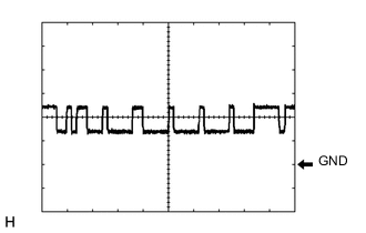
Waveform 1
-
CAN communication signal
Item Content Tester Connection
-
Between G68-8 (CA1P) and G68-28 (GND)
-
Between G68-10 (CA2H) and G68-28 (GND)
Tool Setting 1 V/DIV., 10 μsec./DIV. Condition Engine switch on (IG) Tech Tips
The waveform varies depending on the CAN communication signal.
-
-
-
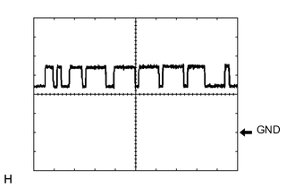
Waveform 2
-
CAN communication signal
Item Content Tester Connection
-
Between G68-9 (CA1N) and G68-28 (GND)
-
Between G68-11 (CA2L) and G68-28 (GND)
Tool Setting 1 V/DIV., 10 μsec./DIV. Condition Engine switch on (IG) Tech Tips
The waveform varies depending on the CAN communication signal.
-
-
-
-
CHECK ECM (for 8GR-FKS)
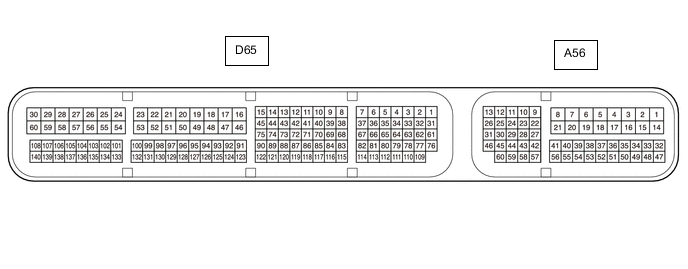
Tester Connection Wiring Color Terminal Description Condition Specified Condition A56-27 (STP) - D65-53 (E1) R - W-B Stop light switch assembly signal Brake pedal depressed 11 to 14 V Brake pedal released Below 1 V A56-42 (ST1-) - D65-53 (E1) GR - W-B Stop light switch assembly signal Engine switch on (IG), brake pedal depressed Below 1 V Engine switch on (IG), brake pedal released 11 to 14 V A56-41 (CCS) - D65-53 (E1) B - W-B Cruise control switch circuit Cruise control switch not pushed 1 MΩ or higher Cruise control main switch pushed Below 2.5 Ω CANCEL switch ON 228 to 252 Ω +RES switch ON 599 to 661 Ω -SET switch ON 1463 to 1617 Ω -
CHECK ECM (for V35A-FTS)
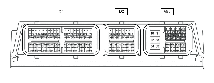
Tester Connection Wiring Color Terminal Description Condition Specified Condition A95-14 (STP) - A95-9 (E1) LA-R - B Stop light switch assembly signal Brake pedal depressed 11 to 14 V Brake pedal released Below 1 V A95-13 (ST1-) - A95-9 (E1) LA-B - B Stop light switch assembly signal Engine switch on (IG), brake pedal depressed Below 1 V Engine switch on (IG), brake pedal released 11 to 14 V A95-61 (CCS) - A95-62 (ECCS) B - BR Cruise control switch circuit Cruise control switch not pushed 1 MΩ or higher Cruise control main switch pushed Below 2.5 Ω CANCEL switch ON 228 to 252 Ω +RES switch ON 599 to 661 Ω -SET switch ON 1463 to 1617 Ω A95-9 (E1) - Body ground B - Body ground ECM ground Always Below 1 Ω -
CHECK MILLIMETER WAVE RADAR SENSOR

Tester Connection Wiring Color Terminal Description Condition Specified Condition C6-1 (SGND) - Body ground W-B - Body ground Ground Always Below 1 Ω C6-2 (CA2L) - C6-1 (SGND) W - W-B CAN communication signal Engine switch on (IG) Pulse generation
(See waveform 2)
C6-3 (CA2H) - C6-1 (SGND) V - W-B CAN communication signal Engine switch on (IG) Pulse generation
(See waveform 1)
C6-5 (CA1P) - C6-1 (SGND) B - W-B CAN communication signal Engine switch on (IG) Pulse generation
(See waveform 1)
C6-6 (CA1N) - C6-1 (SGND) W - W-B CAN communication signal Engine switch on (IG) Pulse generation
(See waveform 2)
C6-8 (IGB) - C6-1 (SGND) R - W-B Power source Engine switch on (IG) 10.5 to 16 V
-
Waveform 1
-
CAN communication signal
Item Content Tester Connection
-
Between C6-3 (CA2H) and C6-1 (SGND)
-
Between C6-5 (CA1P) and C6-1 (SGND)
Tool Setting 1 V/DIV., 10 μsec./DIV. Condition Engine switch on (IG) Tech Tips
The waveform varies depending on the CAN communication signal.
-
-
-

Waveform 2
-
CAN communication signal
Item Content Tester Connection
-
Between C6-2 (CA2L) and C6-1 (SGND)
-
Between C6-6 (CA1N) and C6-1 (SGND)
Tool Setting 1 V/DIV., 10 μsec./DIV. Condition Engine switch on (IG) Tech Tips
The waveform varies depending on the CAN communication signal.
-
-
-