CYLINDER HEAD INSTALLATION
-
INSTALL CYLINDER HEAD GASKET
-
Check piston protrusion for each cylinder.
-
Clean the cylinder block with solvent.
-
Set the piston of the cylinder to be measured to slightly before TDC.
-
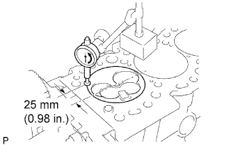
Place a dial indicator on the cylinder block, and set the measuring tip as shown in the illustration.
-
Set the dial indicator at 0 mm (0 in.).
Tech Tips
-
Use a dial indicator measuring tip as shown in the illustration.
-
Make sure that the measuring tip is square to the cylinder block gasket surface and piston head when taking the measurements.
-
-
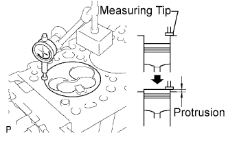
Find where the piston head protrudes most by slowly turning the crankshaft clockwise and counterclockwise.
-
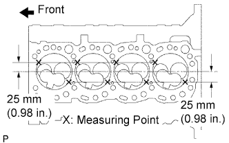
Measure the protrusion of each cylinder at 2 places as shown in the illustration, making a total of 8 measurements.
-
For the piston protrusion value of each cylinder, use the average of the 2 measurements of each cylinder.
Standard piston protrusion 0.73 to 0.98 mm (0.0287 to 0.0386 in.) Tech Tips
If the protrusion is not as specified, remove the piston and connecting rod assembly and reinstall it.
-
-
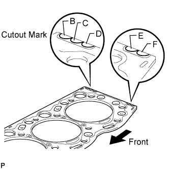
Select a new cylinder head gasket.
Tech Tips
There are 3 sizes of new cylinder head gaskets, marked "B", "D" or "F" accordingly.
Cylinder head gasket thickness Cutout Mark Thickness B 1.40 to 1.50 mm (0.0551 to 0.0591 in.) C 1.45 to 1.55 mm (0.0570 to 0.0610 in.) D 1.50 to 1.60 mm (0.0591 to 0.0630 in.) E 1.55 to 1.65 mm (0.0610 to 0.0650 in.) F 1.60 to 1.70 mm (0.0630 to 0.0669 in.)
-
Select the largest piston protrusion value from the measurements made, then select a new appropriate gasket according to the table below.
Use gasket size Gasket Size Piston Protrusion Use B 0.73 to 0.78 mm (0.0287 to 0.0307 in.) Use C 0.78 to 0.83 mm (0.0307 to 0.0327 in.) Use D 0.83 to 0.88 mm (0.0327 to 0.0346 in.) Use E 0.88 to 0.93 mm (0.0346 to 0.0366 in.) Use F 0.93 to 0.98 mm (0.0366 to 0.0386 in.)
-
-
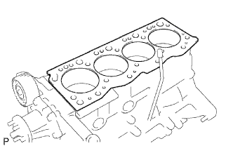
Place a new cylinder head gasket in position on the cylinder block.
Note
Be careful of the installation direction.
-
-
INSTALL CYLINDER HEAD SUB-ASSEMBLY
Tech Tips
-
Set the No. 1 cylinder to 90° BTDC/compression to avoid interference with the piston top and valve head.
-
The cylinder head bolts are tightened in 3 progressive steps.
-
If any bolt is broken or deformed, replace it.
-
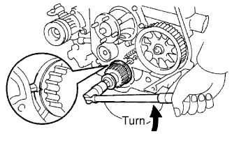
Using the crankshaft pulley bolt, turn the crankshaft 90° counterclockwise, and align the timing mark of the crankshaft timing pulley with the protrusion of the timing belt case.
-
Place the cylinder head in position on the cylinder head gasket.
-
Apply a light coat of engine oil on the threads and under the heads of the cylinder head bolts.
-
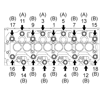
Install and uniformly tighten the 18 cylinder head bolts, in several passes in the sequence shown in the illustration.
- Torque:
- 78 N*m { 800 kgf*cm, 58 ft.*lbf }
Bolt length A 107 mm (4.21 in.) Bolt length B 127 mm (5.00 in.) If any one of the cylinder head bolts does not meet the torque specification, replace the cylinder head bolt.
-
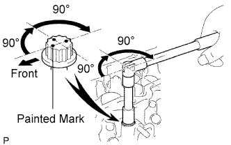
Mark the front of the cylinder head bolt with paint.
-
Retighten the cylinder head bolts 90° in the numerical order shown.
-
Retighten the cylinder head bolts by an additional 90°.
-
Check that the painted mark is now facing rearward.
-
-
INSTALL CAMSHAFT
-
Set the No. 1 cylinder to 90° BTDC/compression.
Tech Tips
Set the No. 1 cylinder to 90° BTDC/compression to avoid interference with the piston top and valve head.
-
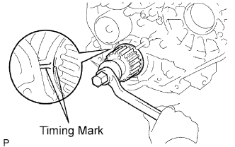
Using the crankshaft pulley bolt, turn the crankshaft, and put the timing mark of the crankshaft timing pulley with the protrusion of the timing belt case.
-
-
Install the camshaft.
Note
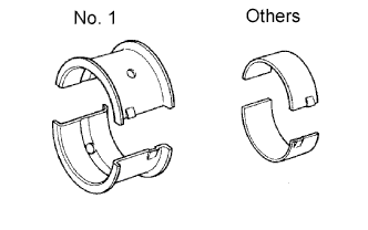
Different bearings are used for the No. 1 and others.
-
Install the 10 bearings to the bearing caps and cylinder head.
-
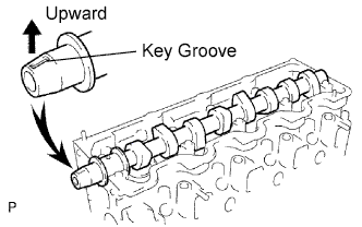
Place the camshaft on the cylinder head, with the key groove facing upward.
-
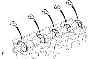
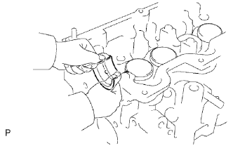
Install the 5 bearing caps in their proper locations.
-
Apply a light coat of engine oil to the threads and under the heads of the bearing cap bolts.
-
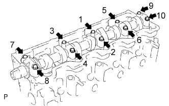
Install and uniformly tighten the 10 bearing cap bolts, in several steps, in the sequence shown.
- Torque:
- 25 N*m { 255 kgf*cm, 18 ft.*lbf }
-
-
-
INSTALL CAMSHAFT OIL SEAL RETAINER
-
Install a new gasket and the retainer with the 4 bolts.
- Torque:
- 18 N*m { 184 kgf*cm, 13 ft.*lbf }
-
-
INSTALL NO. 2 TIMING BELT COVER
-
Install the timing belt cover with the 4 bolts.
- Torque:
- 18 N*m { 184 kgf*cm, 13 ft.*lbf }
-
-
INSTALL CAMSHAFT TIMING PULLEY
-
Install the woodruff key to the key groove of the camshaft.
-
Align the pulley set key with the timing mark facing outward.
-
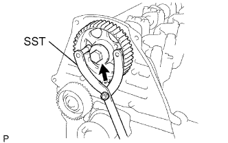
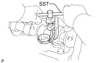
Using SST, install the pulley with the bolt.
- SST
- 09960-10010 ( 09962-01000, 09963-01000 )
- Torque:
- 98 N*m { 1,000 kgf*cm, 72 ft.*lbf }
-
-
INSPECT VALVE CLEARANCE
-
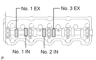
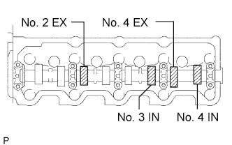
Check only the valves indicated in the illustration.
-
Using a feeler gauge, measure the clearance between the valve lifter and camshaft.
-
Record the out-of-specification valve clearance measurements. They will be used later to determine the required replacement adjusting shim.
Standard valve clearance (Cold) Intake Exhaust 0.20 to 0.30 mm (0.008 to 0.012 in.) 0.40 to 0.50 mm (0.016 to 0.020 in.)
-
-
Turn the crankshaft one revolution (360°) and align the mark as above.
-
Check only the valves indicated in the illustration. Measure the valve clearance. (see procedure in the first step)
Standard valve clearance (Cold) Intake Exhaust 0.20 to 0.30 mm (0.008 to 0.012 in.) 0.40 to 0.50 mm (0.016 to 0.020 in.)
-
-
ADJUST VALVE CLEARANCE
-
Remove the adjusting shim.
-
Turn the crankshaft so that the cam lobe of the camshaft on the adjusting valve points upward.
-
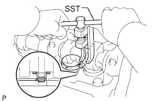
Using SST, press down the valve lifter.
- SST
- 09248-64011
-
Position the notch of the valve lifter with it facing the exhaust manifold side.
-
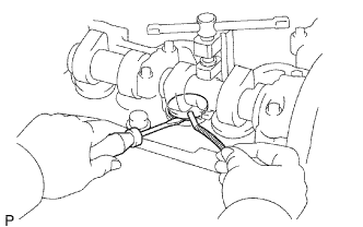
Remove the adjusting shim with a screwdriver and magnetic finger.
-
-
Determine the replacement adjusting shim size by following the formula or charts:
-
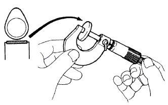
Using a micrometer, measure the thickness of the removed shim.
-
Calculate the thickness of a new shim so that the valve clearance comes within the specified value.
T = Thickness of removed shim
A = Measured valve clearance
N = Thickness of new shim
Intake N = T + (A - 0.25 mm (0.010 in.)) Exhaust N = T + (A - 0.45 mm (0.018 in.)) -
Select a new shim with a thickness as close as possible to the calculated value.
Tech Tips
Shims are available in 17 sizes in increments of 0.05 mm (0.0020 in.), from 2.50 mm (0.0984 in.) to 3.30 mm (0.1299 in.).
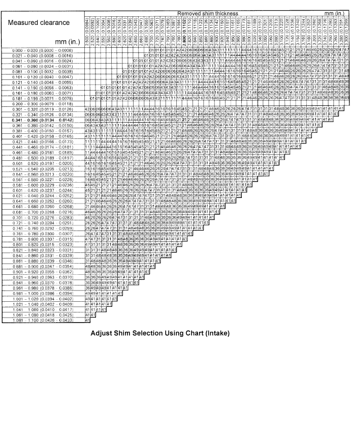
New shim thickness mm (in.) Shim No. Thickness Shim No. Thickness 01 2.50 mm (0.0984 in.) 46 2.95 mm (0.1161 in.) 42 2.55 mm (0.1004 in.) 26 3.00 mm (0.1181 in.) 06 2.60 mm (0.1024 in.) 47 3.05 mm (0.1201 in.) 43 2.65 mm (0.1043 in.) 31 3.10 mm (0.1220 in.) 11 2.70 mm (0.1063 in.) 48 3.15 mm (0.1240 in.) 44 2.75 mm (0.1083 in.) 36 3.20 mm (0.1260 in.) 16 2.80 mm (0.1102 in.) 49 3.25 mm (0.1280 in.) 45 2.85 mm (0.1122 in.) 41 3.30 mm (0.1299 in.) 21 2.90 mm (0.1142 in.) - - Standard intake valve clearance (Cold) 0.20 to 0.30 mm (0.008 to 0.012 in.) EXAMPLE:
The 2.800 mm (0.1102 in.) shim is installed and the measured clearance is 0.350 mm (0.0138 in.). Replace the 2.800 mm (0.1102 in.) shim with a No. 21 shim.
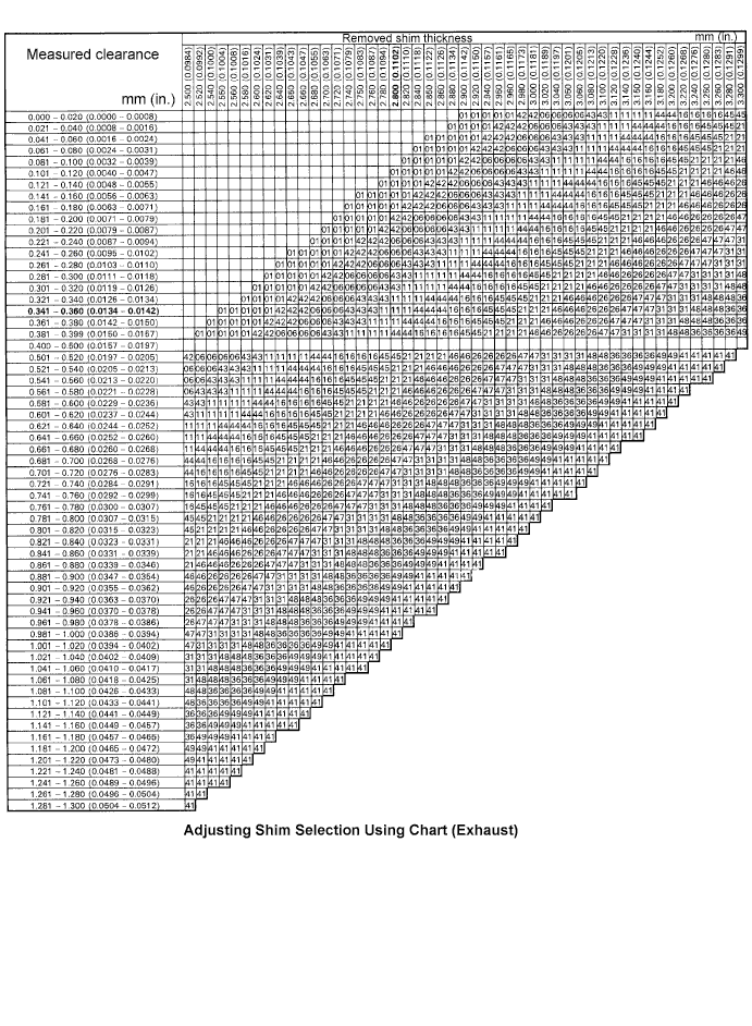
New shim thickness mm (in.) Shim No. Thickness Shim No. Thickness 01 2.50 mm (0.0984 in.) 46 2.95 mm (0.1161 in.) 42 2.55 mm (0.1004 in.) 26 3.00 mm (0.1181 in.) 06 2.60 mm (0.1024 in.) 47 3.05 mm (0.1201 in.) 43 2.65 mm (0.1043 in.) 31 3.10 mm (0.1220 in.) 11 2.70 mm (0.1063 in.) 48 3.15 mm (0.1240 in.) 44 2.75 mm (0.1083 in.) 36 3.20 mm (0.1260 in.) 16 2.80 mm (0.1102 in.) 49 3.25 mm (0.1280 in.) 45 2.85 mm (0.1122 in.) 41 3.30 mm (0.1299 in.) 21 2.90 mm (0.1142 in.) - - Standard exhaust valve clearance (Cold) 0.40 to 0.50 mm (0.016 to 0.020 in.) EXAMPLE:
The 2.800 mm (0.1102 in.) shim is installed and the measured clearance is 0.350 mm (0.0138 in.). Replace the 2.800 mm (0.1102 in.) shim with a No. 11 shim.
-
-
Install a new adjusting shim.
-
Place a new adjusting shim on the valve lifter.
-
Remove the SST.
-
-
Recheck the valve clearance.
-
-
INSTALL CYLINDER HEAD COVER SUB-ASSEMBLY
-
Remove any old packing (FIPG) material.
-
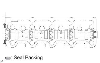
Apply seal packing to the cylinder head as shown in the illustration.
Seal packing Toyota Genuine Seal Packing Black, Three Bond 1207B or equivalent -
Install the gasket to the cylinder head cover.
-
Install the cylinder head cover with the 9 bolts and nut. Uniformly tighten the bolts and nuts in several steps.
- Torque:
- 12 N*m { 122 kgf*cm, 9 ft.*lbf }
-
-
INSTALL INTAKE MANIFOLD
-
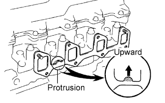
Install a new gasket to the cylinder head with the protrusion facing upward.
-
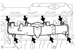
Install the intake manifold with the 6 bolts and 2 nuts. Uniformly tighten the bolts and nuts in several steps.
- Torque:
- 23.5 N*m { 240 kgf*cm, 17 ft.*lbf }
-
-
INSTALL EXHAUST MANIFOLD
-
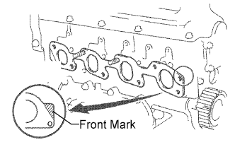
Install a new gasket to the cylinder head.
Tech Tips
Be sure to install a new gasket in the correct direction as shown in the illustration.
-
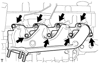
Install the exhaust manifold with the 6 bolts and 2 new nuts. Uniformly tighten the bolts and nuts in several steps.
- Torque:
- 52 N*m { 530 kgf*cm, 38 ft.*lbf }
-
-
INSTALL WATER OUTLET HOUSING
-
Install a new gasket to the cylinder head.
-
Install the outlet hosing with the 3 bolts
- Torque:
- 19 N*m { 195 kgf*cm, 14 ft.*lbf }
-
-
INSTALL NO. 1 GLOW PLUG CONNECTOR
-
Install the glow plug connector by uniformly tightening the 4 nuts.
- Torque:
- 1.0 N*m { 10 kgf*cm, 9 in.*lbf }
-
Install the 4 screw grommets.
-
Install the wire harness with the nut.
- Torque:
- 8.4 N*m { 85 kgf*cm, 74 in.*lbf }
-
-
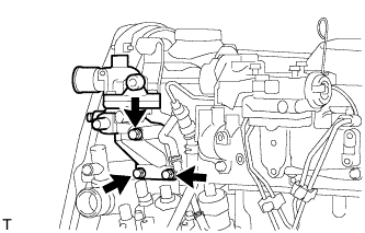
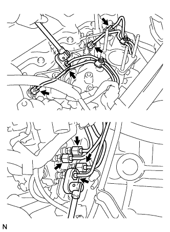
INSTALL INJECTION PIPE SET
-
Connect the 2 lower clamps on the intake manifold.
-
Using a union nut wrench, install the 4 injection pipes.
- Torque:
- 24.5 N*m { 250 kgf*cm, 18 ft.*lbf }
-
Secure the injection pipes with the 2 upper pipe clamps and 2 nuts.
- Torque:
- 5.0 N*m { 51 kgf*cm, 44 in.*lbf }
-
-
INSTALL NO. 1 EXHAUST MANIFOLD HEAT INSULATOR
-
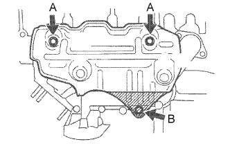
Install the heat insulator with the 3 bolts.
- Torque:
- 18 N*m { 185 kgf*cm, 13 ft.*lbf, for bolt A }
- 19 N*m { 195 kgf*cm, 14 ft.*lbf, for bolt B }
-
-
INSTALL VENTURI ASSEMBLY
-
Place a new gasket and the venturi on the intake manifold.
-
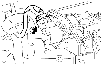
Connect the throttle control motor connector.
-
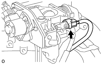
Connect the throttle open switch connector.
-
-
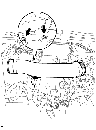
INSTALL INTAKE PIPE ASSEMBLY
-
Install the intake pipe with the 2 bolts.
- Torque:
- 18 N*m { 184 kgf*cm, 13 ft.*lbf }
-
Tighten the intake pipe clamp.
-
-
INSTALL TIMING BELT
-
Install the timing belt Click here.
-
-
CONNECT HEATER WATER HOSE INLET A
-
Connect the water inlet Click here.
-
-
CONNECT HEATER WATER OUTLET HOSE A
-
Connect the water outlet Click here.
-
-
INSTALL COMPRESSOR MOUNTING BRACKET (w/ Air Conditioning System)
-
Temporarily install the compressor mounting bracket with the 4 bolts.
-
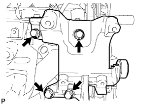
Using several steps, uniformly install and tighten the 4 bolts.
- Torque:
- 85 N*m { 870 kgf*cm, 63 ft.*lbf }
-
Temporarily install the spacer with the bolt.
-
-
INSTALL COMPRESSOR AND MAGNET CLUTCH (w/ Air Conditioning System)
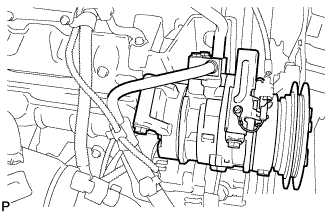
-
Install the compressor with the 4 bolts.
- Torque:
- 50 N*m { 510 kgf*cm, 37 ft.*lbf }
-
-
INSTALL AIR CLEANER ASSEMBLY
-
Install the cleaner with the 2 bolts.
- Torque:
- 14 N*m { 143 kgf*cm, 10 ft.*lbf }
-
Connect the connector to the IAT meter.
-
Connect the hose clamp.
-
-
INSTALL FAN SHROUD
-
Install the fan shroud Click here.
-
-
CONNECT RADIATOR HOSE INLET
-
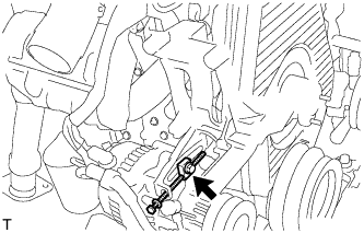
INSTALL FRONT EXHAUST PIPE ASSEMBLY
-
Temporally install the pipe support and clamp with the bolt.
-
Install a new gasket to the exhaust manifold.
-
Install the front exhaust pipe to the exhaust manifold with the 3 nuts. Alternately tighten the bolts in several passes.
- Torque:
- 62 N*m { 632 kgf*cm, 46 ft.*lbf }
-
Install the stay to the transmission with the 2 bolts.
- Torque:
- 71 N*m { 724 kgf*cm, 52 ft.*lbf }
-
Install the clamp with the bolt.
- Torque:
- 19 N*m { 194 kgf*cm, 14 ft.*lbf }
-
-
ADD ENGINE COOLANT
-
Tighten the radiator drain cock plug by hand.
-
Tighten the cylinder block drain cock plug.
- Torque:
- 57 N*m { 581 kgf*cm, 42 ft.*lbf }
-
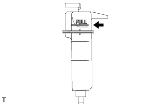
Fill the radiator with TOYOTA Super Long Life Coolant (SLLC) to the reservoir tank's FULL line.
Standard capacity 9.4 liters (9.9 US qts, 8.3 Imp. qts) Tech Tips
-
TOYOTA vehicles are filled with TOYOTA SLLC at the factory. In order to avoid damage to the engine cooling system and other technical problems, only use TOYOTA SLLC or similar high quality ethylene glycol based non-silicate, non-amine, non-nitrite, non-borate coolant with long-life hybrid organic acid technology (coolant with long-life hybrid organic acid technology consists of a combination of low phosphates and organic acids).
-
Please contact your TOYOTA dealer for further details.
Note
Never use water as a substitute for engine coolant.
-
-
Press the inlet and outlet radiator hoses several times by hand, and then check the level of the coolant.
If the coolant level drops below the FULL line, add TOYOTA SLLC to the FULL line.
-
Install the radiator reservoir cap.
-

Using a wrench, install the vent plug.
- Torque:
- 2.0 N*m { 20 kgf*cm, 18 in.*lbf }
-
Bleed air from the cooling system.
-
Warm up the engine until the thermostat opens. While the thermostat is open, circulate the coolant for several minutes.
-
Maintain the engine speed at 2,500 to 3,000 rpm.
-
Press the inlet and outlet radiator hoses several times by hand to bleed air.
CAUTION:
When pressing the radiator hoses:
-
Wear protective gloves.
-
Be careful as the radiator hoses are hot.
-
Keep your hands away from the radiator fan.
-
-
Stop the engine and wait until the coolant cools down to ambient temperature.
CAUTION:
Do not remove the radiator reservoir cap while the engine and radiator are still hot. Pressurized, hot engine coolant and steam may be released and cause serious burns.
-
-
After the coolant cools down, check that the coolant level is at the FULL line.
If the coolant level is below the low line, add TOYOTA SLLC to the FULL line.
-
-
ADD FUEL
-
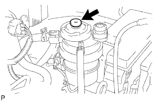
ADD ENGINE OIL
-
Add fresh engine oil.
Standard capacity Item Specified Condition Drain and refill with oil filter change 7.2 liters (7.6 US qts, 6.3 Imp. qts) Drain and refill without oil filter change 6.7 liters (7.1 US qts, 5.9 Imp. qts) Dry fill 8.4 liters (8.9 US qts, 7.4 Imp. qts) -
Reinstall the oil filler cap.
-
-
TIGHTEN FUEL TANK CAP ASSEMBLY
-
BLEED AIR FROM FUEL SYSTEM
-
Using the hand pump, bleed air from the fuel system until pumping becomes difficult.
-
-
CONNECT CABLE TO NEGATIVE BATTERY TERMINAL
-
PERFORM INITIALIZATION
-
Perform initialization Click here.
-
-
CHECK FOR ENGINE COOLANT LEAKS
Note
Do not remove the radiator reservoir cap while the engine and radiator are still hot. Pressurized, hot engine coolant and steam may be released and cause serious burns.
-
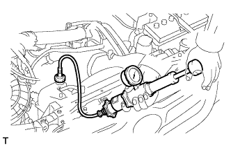
Fill the radiator with coolant and attach a radiator cap tester.
-
Warm up the engine.
-
Using the radiator cap tester, increase the pressure inside the radiator to 118 kPa (1.2 kgf/cm2, 17.1 psi), and check that the pressure does not drop.
If the pressure drops, check the hoses, radiator and water pump for leaks.
If no external leaks are found, check the cylinder block and head.
-
-
CHECK FOR FUEL LEAKS
-
CHECK FOR EXHAUST GAS LEAKS
-
INSPECT IDLE ENGINE SPEED
-
Warm up the engine.
-
When using the intelligent tester:
-
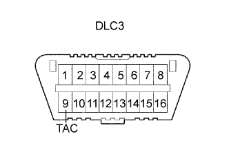
Connect the intelligent tester to the DLC3.
-
Measure the idle speed.
Standard idle speed 720 to 820 rpm (A/C OFF) 750 to 850 rpm (A/C ON) Tech Tips
Refer to the intelligent tester operator's manual for further details.
-
-
When not using the intelligent tester:
-
Using SST, connect the tachometer test probe to terminal 9 (TAC) of the DLC3.
- SST
- 09843-18040
-
Measure the idle speed.
Standard idle speed 720 to 820 rpm (A/C OFF) 750 to 850 rpm (A/C ON) Note
Switch off all accessories.
-
-
-
INSPECT MAXIMUM ENGINE SPEED
-
Start the engine.
-
Fully depress the accelerator pedal.
-
Measure the maximum speed.
Maximum speed 4,850 to 4,950 rpm
-
-
INSTALL NO. 2 ENGINE UNDER COVER (for 4WD)
-
Install the under cover with the 4 bolts.
- Torque:
- 28 N*m { 286 kgf*cm, 21 ft.*lbf }
-
-
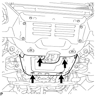
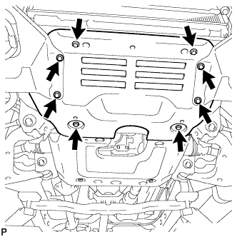
INSTALL NO. 1 ENGINE UNDER COVER (for 4WD)
-
Install the under cover with the 8 bolts.
- Torque:
- 28 N*m { 286 kgf*cm, 21 ft.*lbf }
-