COMBUSTION TYPE POWER HEATER SYSTEM TERMINALS OF ECU
INSPECT HEATER ASSEMBLY

Measure the voltage and resistance, and check for pulses according to the value(s) in the table below.
Terminal No. (Symbol)
Wiring Color
Terminal Description
Condition
Specified Condition
A42-1 (E) - Body ground
W-B - Body ground
Ground for main power supply
Always
Below 1 Ω
A42-2 (L) - Body ground
G - Body ground
Fuel pump operation signal
Engine running
Heater switch assembly: On
Pulse generation
(See waveform 1)
A42-3 (IG) - Body ground
Y - Body ground
Power heater operating signal
Ignition switch ON
Heater switch assembly: On
11 to 14 V
A42-3 (IG) - Body ground
Y - Body ground
Power heater operating signal
Ignition switch off
Heater switch assembly: Off
Below 1 V
A42-5 (B) - Body ground
W - Body ground
Power source
Always
11 to 14 V
A42-8 (+) - Body ground
Y - Body ground
Engine operating signal
Engine running
(Generator assembly: Operating)
11 to 14 V
-
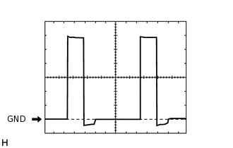
Waveform 1:
Table 1. Heater Fuel Pump Control Signal Item
Content
Terminal No. (Symbol)
A42-2 (L) - Body ground
Tool Setting
2 V/DIV., 20 ms/DIV.
Vehicle Condition
Engine running
Heater switch assembly: On