AUDIO AND VISUAL SYSTEM
-
FUNCTION
-
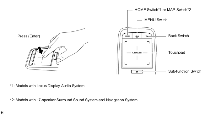
The remote touch (remote operation controller assembly) consists of the switches and touchpad.
-
Touchpad Control
-
A stabilizer structure is used to distribute force evenly when the surface of the touchpad is pressed. No matter what area of the touchpad is pressed, the operation is recognized without misoperation.
-
The touchpad has an operation detection area. Also, the position coordinates from 0 to 255 for both the horizontal axis (x-axis) and vertical axis (y-axis) of the detection area are output to the radio receiver assembly.
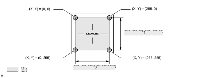
*1 Vertical Axis (Y-axis) *2 Detection Area *3 Horizontal Axis (X-axis) -
The cursor or pointer is displayed on the screen of the multi-display at the corresponding coordinates of the horizontal axis (x-axis) and vertical axis (y-axis) where the operation occurred.
Figure 1. Map Screen Related Screen Coordinates Image (Models with Navigation System)
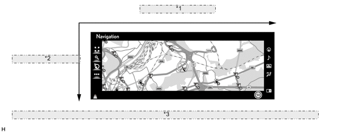
*1 Horizontal Axis (X-axis) *2 Vertical Axis (Y-axis) *3 The illustration shown is an example only. The illustration may differ from the actual vehicle screen. -
The touchpad recognizes the contact of a finger or multiple fingers based on the following detection conditions:
Tech Tips
The values listed in the following table are the specifications. Actual detected values may differ depending on the temperature, etc.
Figure 2. Touchpad Detection Conditions Image
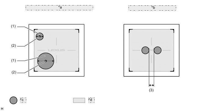
*a Detection of finger and finger location coordinates *b Multiple finger detection *c Finger Contact Area *d Detection Area Touchpad Detection Condition NO. Detection Item Details (1) Finger Detection A finger contact area diameter of 7.4 mm (0.29 in.) to 31.5 mm (1.24 in.) can be detected. Anything outside of that range will not be detected. (2) Detected Coordinates of Finger The coordinates at the center of the finger contact area are output as the touch location. (3) Multiple Finger Detection For multiple finger detection, a distance of 6 mm (0.23 in.) or more is required between the contact area of each finger.
-
-
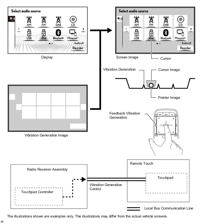
Vibration Control
-
To provide feedback to the user's hand, the remote touch (remote operation controller assembly) uses an internal motor to generate vibrations for the touchpad when selected icons or buttons change.
Figure 3. Vibration Control Image
-
-
Pull-in Control
-
The button whose center is closest to the current pointer position is judged to be the pull-in button, which pulls the pointer toward the center of the button.
-
In the following illustration, since the distance between the current pointer position and the center of button A is smaller than the distance between the current pointer position and the center of button B, the pointer is pulled to button A.
-
When the pointer position changes as shown in the following illustration, the vibrations are generated on the touchpad.
Figure 4. Pull-in Control Image

*1 Pointer *2 Button B *3 Button A *4 Vibration generated on touchpad
-
-
Frame Area Control
-
A frame area surrounds all screens. The frame area prevents the pointer from moving outside the screen.
Figure 5. Home Screen related Frame Area Control Image (Models with Lexus Display Audio System)
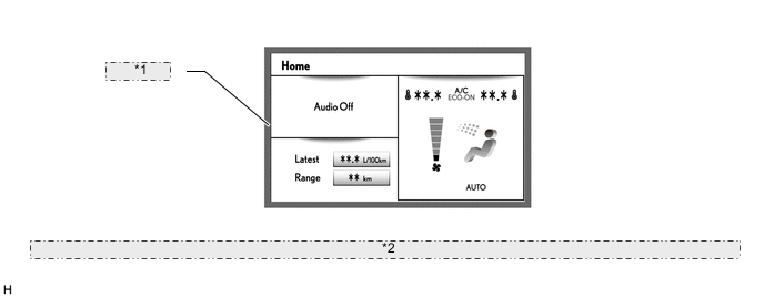
*1 Frame area *2 The illustration shown is an example only. The illustration may differ from the actual vehicle screen.
-
-
-
OPERATION
-
Touchpad Operation
-
Touchpad operations are displayed by the system highlighting the screen buttons of the multi-display or moving the pointer.
-
When the touchpad is operated, the touchpad calculates the difference based on the previous pointer position coordinates sent to the radio receiver assembly and sends the result to the radio receiver assembly.
Figure 6. Map Screen Related Pointer Operation Image (Models with Navigation System)
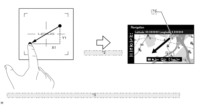
*1 Coordinates (X0, Y0) *2 Sends new coordinate as (X0+X1, Y0+Y1) *3 The illustrations shown are examples only. The illustrations may differ from the actual vehicle screens.
-
-