FUEL SYSTEM DETAILS
-
CONSTRUCTION
-
Fuel Injector Assembly
-
A 12-hole fuel injector assembly with optimized fuel flow amount is used to improve the atomization of fuel.
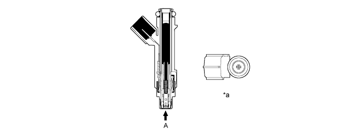
Text in Illustration *a View from A - -
-
-
Fuel Delivery Pipe Sub-assembly
-
The fuel delivery pipe sub-assembly is made of plastic to reduce weight.
-
The right and left fuel delivery pipes are connected by a nylon tube.
-
The pulsation damper is sealed with an O-ring and secured with a holder.
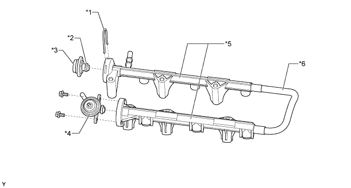
Text in Illustration *1 Holder *2 O-ring *3 Pulsation Damper *4 Fuel Pressure Regulator Assembly *5 Fuel Delivery Pipe Sub-assembly *6 Nylon Tube
-
-
Fuel Suction with Pump and Gauge Tube Assembly
-
A compact fuel suction with pump and gauge tube assembly is used. Its basic components are a fuel pump and a fuel sender gauge assembly.
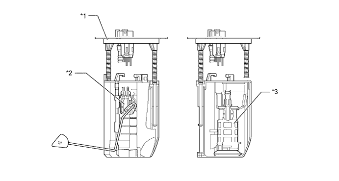
Text in Illustration *1 Fuel Suction with Pump and Gauge Tube Assembly *2 Fuel Sender Gauge Assembly *3 Fuel Pump - -
-
-