KNOCK SENSOR INSTALLATION
PROCEDURE
-
INSTALL KNOCK CONTROL SENSOR
-
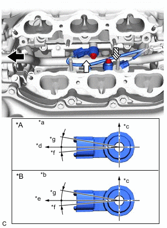
*A for Bank 1 *B for Bank 2 *a View A *b View B *c Top *d Engine Front *e Engine Rear *f 5° *g 10° 
Engine Front 
View A 
View B Temporarily install the 2 knock control sensors to the cylinder block sub-assembly with the 2 bolts so that the knock control sensor installation position is as shown in the illustration.
Note
-
If a knock control sensor has been struck or dropped, replace it.
-
Make sure that the knock control sensor is installed in the correct position.
-
-
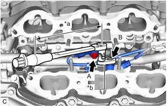
*a Torque Wrench Fulcrum Length *b 10 mm Union Nut Wrench Tighten the bolt (A).
- Torque:
- 20 N*m { 204 kgf*cm, 15 ft.*lbf }
-
Using a 10 mm union nut wrench, tighten the bolt (B).
- Torque:
- Specified tightening torque
- 20 N*m { 204 kgf*cm, 15 ft.*lbf }
Tech Tips
-
Calculate the torque wrench reading when changing the fulcrum length of the torque wrench.
-
When using a 10 mm union nut wrench (fulcrum length of 22 mm (0.866 in.)) + torque wrench (fulcrum length of 162 mm (6.38 in.)):
17.6 N*m (179 kgf*cm, 13 ft.*lbf)
-
Connect the 2 knock control sensor connectors.
-
-
INSTALL FUEL DELIVERY PIPE
-
PERFORM INITIALIZATION
-
Perform "Inspection After Repair" after replacing a knock control sensor.
-