WIRELESS DOOR LOCK CONTROL SYSTEM(w/ Entry and Start System) No Answer-Back
| DTC Code | DTC Name |
|---|---|
| No Answer-Back |
DESCRIPTION
In some cases, the wireless door lock control functions may be normal but the hazard warning light function do not operate. In such cases, the hazard warning light signal outputs from the body ECU may be malfunctioning.
WIRING DIAGRAM
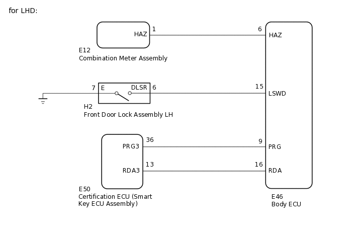

CAUTION / NOTICE / HINT
When replacing the certification ECU (smart key ECU assembly), refer to Service Bulletin.
Before performing the inspection, check that DTC B27B0 (Entry and Start System) is not output.
PROCEDURE
CHECK WIRELESS DOOR LOCK CONTROL FUNCTION
Check the wireless door lock control function using the electrical key transmitter sub-assembly.
Result
Result
Proceed to
Wireless door lock/unlock functions operate properly.
A
Wireless door lock/unlock functions do not operate properly.
B
INSPECT FRONT DOOR LOCK ASSEMBLY
for LHD
Remove the front door lock assembly LH
Inspect the front door lock assembly LH.
for RHD
Remove the front door lock assembly RH
Inspect the front door lock assembly RH.
Result
Result
Proceed to
OK
A
NG (for LHD)
B
NG (for RHD)
C
CHECK HARNESS AND CONNECTOR (FRONT DOOR LOCK ASSEMBLY - BODY ECU)
Disconnect the H2 front door lock assembly LH connector.*1
Disconnect the G2 front door lock assembly RH connector.*2
*1: for LHD
*2: for RHD
Disconnect the E46 body ECU connector.
Measure the resistance according to the value(s) in the table below.
Standard Resistance
Table 1. for LHD Tester Connection
Condition
Specified Condition
H2-6 (DLSR) - E46-15 (LSWD)
Always
Below 1 Ω
H2-7 (E) - Body ground
Always
Below 1 Ω
H2-6 (DLSR) or E46-15 (LSWD) - Body ground
Always
10 kΩ or higher
Standard Resistance
Table 2. for RHD Tester Connection
Condition
Specified Condition
G2-9 (DLSR) - E46-15 (LSWD)
Always
Below 1 Ω
G2-8 (E) - Body ground
Always
Below 1 Ω
G2-9 (DLSR) or E46-15 (LSWD) - Body ground
Always
10 kΩ or higher
Result
Proceed to
OK
NG
NG REPAIR OR REPLACE HARNESS OR CONNECTOR
CHECK HAZARD WARNING LIGHTS OPERATION
Check that the hazard warning lights blink when the hazard warning signal switch is pressed.
OK
Hazard warning lights blink.
Result
Proceed to
OK
NG
CHECK HARNESS AND CONNECTOR (COMBINATION METER ASSEMBLY - BODY ECU)
Disconnect the E12 combination meter assembly connector.
Disconnect the E46 body ECU connector.
Measure the resistance according to the value(s) in the table below.
Standard Resistance
Tester Connection
Condition
Specified Condition
E12-1 (HAZ) - E46-6 (HAZ)
Always
Below 1 Ω
E12-1 (HAZ) or E46-6 (HAZ) - Body ground
Always
10 kΩ or higher
Result
Proceed to
OK
NG
NG REPAIR OR REPLACE HARNESS OR CONNECTOR