INPUT SHAFT INSPECTION
PROCEDURE
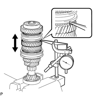
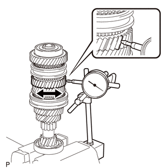
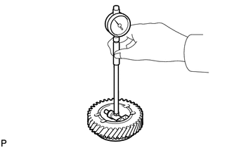
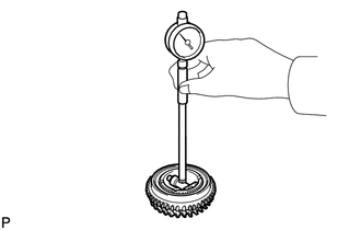
INSPECT 6TH GEAR THRUST CLEARANCE
-

Using a dial indicator, measure the 6th gear thrust clearance.
Standard Clearance
0.15 to 0.43 mm (0.00591 to 0.0169 in.)
Maximum Clearance
0.43 mm (0.0169 in.)
If the clearance exceeds the maximum, replace the No. 3 transmission clutch hub, 6th gear sub-assembly or input shaft.
-
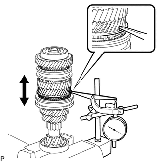
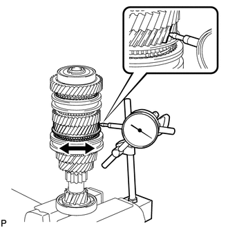
INSPECT 5TH GEAR THRUST CLEARANCE
-
Using a dial indicator, measure the 5th gear thrust clearance.
Standard Clearance
0.15 to 0.43 mm (0.00591 to 0.0169 in.)
Maximum Clearance
0.43 mm (0.0169 in.)
If the clearance exceeds the maximum, replace the No. 3 transmission clutch hub, 5th gear or input shaft.
-
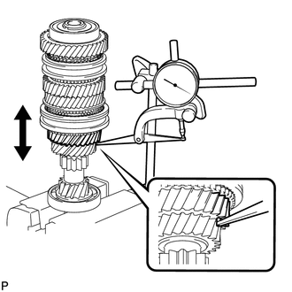
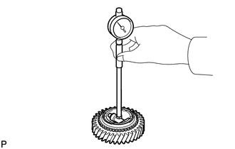
INSPECT 4TH GEAR THRUST CLEARANCE
-
Using a dial indicator, measure the 4th gear thrust clearance.
Standard Clearance
0.15 to 0.56 mm (0.00591 to 0.0220 in.)
Maximum Clearance
0.56 mm (0.0220 in.)
If the clearance exceeds the maximum, replace the No. 2 transmission clutch hub, 4th gear or input shaft.
-
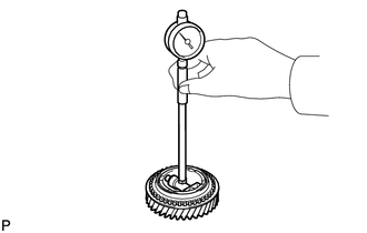
INSPECT 3RD GEAR THRUST CLEARANCE
-
Using a dial indicator, measure the 3rd gear thrust clearance.
Standard Clearance
0.15 to 0.43 mm (0.00591 to 0.0169 in.)
Maximum Clearance
0.43 mm (0.0169 in.)
If the clearance exceeds the maximum, replace the No. 2 transmission clutch hub, 3rd gear or input shaft.
-
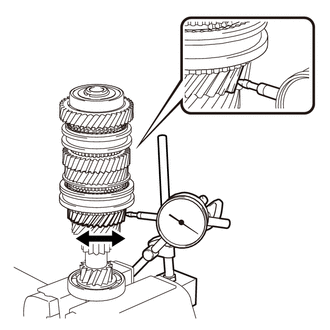
INSPECT 6TH GEAR RADIAL CLEARANCE
-
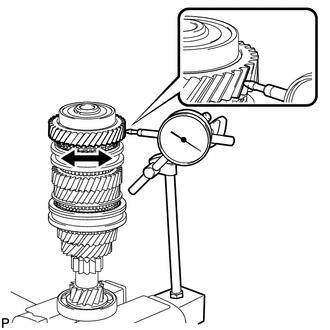
Using a dial indicator, measure the 6th gear radial clearance between the 6th gear sub-assembly and input shaft.
Standard Clearance
0.009 to 0.045 mm (0.000354 to 0.00177 in.)
Maximum Clearance
0.045 mm (0.00177 in.)
If the clearance exceeds the maximum, replace the 6th gear sub-assembly, 6th gear needle roller bearing, inner 6th gear bearing race or input shaft.
-
INSPECT 5TH GEAR RADIAL CLEARANCE
-
Using a dial indicator, measure the 5th gear radial clearance between the 5th gear and input shaft.
Standard Clearance
0.009 to 0.045 mm (0.000354 to 0.00177 in.)
Maximum Clearance
0.045 mm (0.00177 in.)
If the clearance exceeds the maximum, replace the 5th gear, 5th gear needle roller bearing, inner 5th gear bearing race or input shaft.
-
INSPECT 4TH GEAR RADIAL CLEARANCE
-
Using a dial indicator, measure the 4th gear radial clearance between the 4th gear and input shaft.
Standard Clearance
0.009 to 0.050 mm (0.000354 to 0.00197 in.)
Maximum Clearance
0.050 mm (0.00197 in.)
If the clearance exceeds the maximum, replace the 4th gear, 4th gear needle roller bearing or input shaft.
-
INSPECT 3RD GEAR RADIAL CLEARANCE
-
Using a dial indicator, measure the 3rd gear radial clearance between the 3rd gear and input shaft.
Standard Clearance
0.009 to 0.050 mm (0.000354 to 0.00197 in.)
Maximum Clearance
0.050 mm (0.00197 in.)
If the clearance exceeds the maximum, replace the 3rd gear, 3rd gear needle roller bearing or input shaft.
-
INSPECT INPUT SHAFT
-
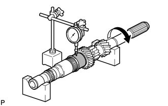
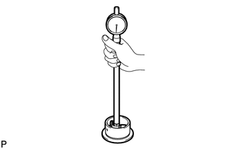
Using a dial indicator, check the input shaft runout.
Maximum Runout
0.03 mm (0.00118 in.)
If the runout exceeds the maximum, replace the input shaft.
-
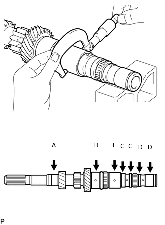
Using a micrometer, measure the outer diameter of the input shaft journal surface at the locations indicated.
Standard Outer Diameter
Part (A)
25.002 to 25.017 mm (0.98433 to 0.98492 in.)
Part (B)
37.485 to 37.500 mm (1.47578 to 1.47638 in.)
Part (C)
31.690 to 31.700 mm (1.24764 to 1.24803 in.)
Part (D)
27.990 to 28.000 mm (1.10197 to 1.10236 in.)
Part (E)
37.496 to 37.500 mm (1.47622 to 1.47638 in.)
Minimum Outer Diameter
Part (A)
25.002 mm (0.98433 in.)
Part (B)
37.485 mm (1.47578 in.)
Part (C)
31.690 mm (1.24764 in.)
Part (D)
27.990 mm (1.10197 in.)
Part (E)
37.496 mm (1.47622 in.)
If any of the outer diameters are less than the minimum, replace the input shaft.
-
INSPECT INNER 6TH GEAR BEARING RACE
-
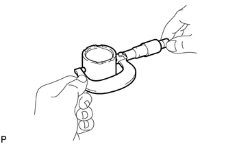
Using a micrometer, measure the outer diameter of the inner 6th gear bearing race.
Standard Outer Diameter
35.09 to 35.10 mm (1.38149 to 1.38189 in.)
Minimum Outer Diameter
35.09 mm (1.38149 in.)
If the outer diameter is less than the minimum, replace the inner 6th gear bearing race.
-
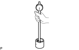
Using a cylinder gauge, measure the inside diameter of the inner 6th gear bearing race.
Standard Inside Diameter
28.005 to 28.020 mm (1.10256 to 1.10315 in.)
Maximum Inside Diameter
28.020 mm (1.10315 in.)
If the inside diameter exceeds the maximum, replace the inner 6th gear bearing race.
-
INSPECT INNER 5TH GEAR BEARING RACE
-
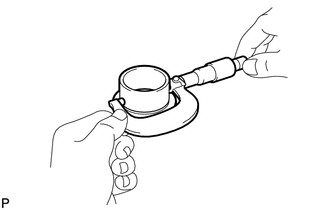
Using a micrometer, measure the outer diameter of the inner 5th gear bearing race.
Standard Outer Diameter
37.49 to 37.50 mm (1.47598 to 1.47638 in.)
Minimum Outer Diameter
37.49 mm (1.47598 in.)
If the outer diameter is less than the minimum, replace the inner 5th gear bearing race.
-
Using a cylinder gauge, measure the inside diameter of the inner 5th gear bearing race.
Standard Inside Diameter
31.705 to 31.720 mm (1.24823 to 1.24882 in.)
Maximum Inside Diameter
31.720 mm (1.24882 in.)
If the inside diameter exceeds the maximum, replace the inner 5th gear bearing race.
-
INSPECT 6TH GEAR SUB-ASSEMBLY
-
Using a cylinder gauge, measure the inside diameter of the 6th gear sub-assembly.
Standard Inside Diameter
40.109 to 40.125 mm (1.57909 to 1.57972 in.)
Maximum Inside Diameter
40.125 mm (1.57972 in.)
If the inside diameter exceeds the maximum, replace the 6th gear sub-assembly.
-
INSPECT 5TH GEAR
-
Using a cylinder gauge, measure the inside diameter of the 5th gear.
Standard Inside Diameter
42.509 to 42.525 mm (1.67358 to 1.67421 in.)
Maximum Inside Diameter
42.525 mm (1.67421 in.)
If the inside diameter exceeds the maximum, replace the 5th gear.
-
INSPECT 4TH GEAR
-
Using a cylinder gauge, measure the inside diameter of the 4th gear.
Standard Inside Diameter
42.509 to 42.511 mm (1.67358 to 1.67366 in.)
Maximum Inside Diameter
42.511 mm (1.67366 in.)
If the inside diameter exceeds the maximum, replace the 4th gear.
-
INSPECT 3RD GEAR
-
Using a cylinder gauge, measure the inside diameter of the 3rd gear.
Standard Inside Diameter
42.509 to 42.525 mm (1.67358 to 1.67421 in.)
Maximum Inside Diameter
42.525 mm (1.67421 in.)
If the inside diameter exceeds the maximum, replace the 3rd gear.
-
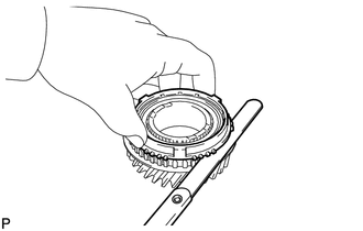
INSPECT NO. 5 SYNCHRONIZER RING (for 5th Gear)
Check for wear and damage.
Coat the 5th gear cone with gear oil.
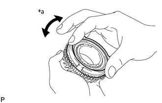
Turn the No. 5 synchronizer ring (for 5th gear) in one direction while pushing it against the 5th gear cone.
-
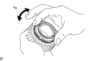
*a
Lock
Check that the No. 5 synchronizer ring (for 5th gear) locks.
If the No. 5 synchronizer ring (for 5th gear) does not lock, replace the No. 5 synchronizer ring (for 5th gear).
-
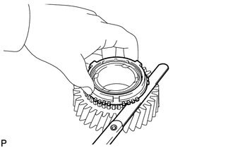
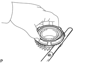
Using a feeler gauge, measure the clearance between the No. 5 synchronizer ring (for 5th gear) and 5th gear spline end.
Standard Clearance
0.73 to 1.53 mm (0.0287 to 0.0602 in.)
Minimum Clearance
0.73 mm (0.0287 in.)
If the clearance is less than the minimum, replace the No. 5 synchronizer ring (for 5th gear).
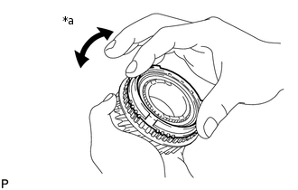
INSPECT NO. 5 SYNCHRONIZER RING (for 6th Gear)
Check for wear and damage.
Coat the 6th gear sub-assembly cone with gear oil.
Turn the No. 5 synchronizer ring (for 6th gear) in one direction while pushing it against the 6th gear sub-assembly cone.
-
*a
Lock
Check that the No. 5 synchronizer ring (for 6th gear) locks.
If the No. 5 synchronizer ring (for 6th gear) does not lock, replace the No. 5 synchronizer ring (for 6th gear).
-
Using a feeler gauge, measure the clearance between the No. 5 synchronizer ring (for 6th gear) and 6th gear sub-assembly spline end.
Standard Clearance
0.73 to 1.53 mm (0.0287 to 0.0602 in.)
Minimum Clearance
0.73 mm (0.0287 in.)
If the clearance is less than the minimum, replace the No. 5 synchronizer ring (for 6th gear).
INSPECT OUTER 2ND SYNCHRONIZER RING
-
*a
Lock
Check for wear and damage.
Coat the 4th gear cone with gear oil.
Turn the outer 2nd synchronizer ring in one direction while pushing it against the 4th gear cone.
Check that the ring locks.
If the outer 2nd synchronizer ring does not lock, replace the outer 2nd synchronizer ring.
-
Using a feeler gauge, measure the clearance between the outer 2nd synchronizer ring and 4th gear spline end.
Standard Clearance
0.78 to 1.58 mm (0.0307 to 0.0622 in.)
Minimum Clearance
0.78 mm (0.0307 in.)
If the clearance is less than the minimum, replace the outer 2nd synchronizer ring.
-
INSPECT NO. 3 SYNCHRONIZER RING
-
*a
Lock
Check for wear and damage.
Coat the 3rd gear cone with gear oil.
Turn the No. 3 synchronizer ring in one direction while pushing it against the 3rd gear cone.
Check that the ring locks.
If the No. 3 synchronizer ring does not lock, replace the No. 3 synchronizer ring.
-
Using a feeler gauge, measure the clearance between the No. 3 synchronizer ring and 3rd gear spline end.
Standard Clearance
0.78 to 1.58 mm (0.0307 to 0.0622 in.)
Minimum Clearance
0.78 mm (0.0307 in.)
If the clearance is less than the minimum, replace the No. 3 synchronizer ring.
-
INSPECT NO. 2 TRANSMISSION HUB SLEEVE
-
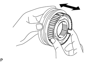
Check the sliding condition between the No. 2 transmission hub sleeve and No. 2 transmission clutch hub.
Check that the edges of the No. 2 transmission hub sleeve splines are not worn down.
-
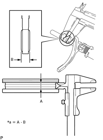
*a
Clearance
Using a vernier caliper, measure the width of the No. 2 transmission hub sleeve groove (A) and thickness of the claw part on the No. 2 gear shift fork (B), and calculate the clearance.
Standard Clearance (A) - (B)
0.1 to 0.5 mm (0.00394 to 0.0197 in.)
If the clearance is out of specification, replace the No. 2 transmission hub sleeve and No. 2 gear shift fork.
-
INSPECT NO. 3 TRANSMISSION HUB SLEEVE
-
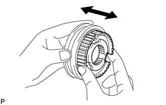
Check the sliding condition between the No. 3 transmission hub sleeve and No. 3 transmission clutch hub.
Check that the edges of the No. 3 transmission hub sleeve splines are not worn down.
-
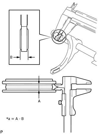
*a
Clearance
Using a vernier caliper, measure the width of the No. 3 transmission hub sleeve groove (A) and thickness of the claw part on the No. 3 gear shift fork (B), and calculate the clearance.
Standard Clearance (A) - (B)
0.1 to 0.5 mm (0.00394 to 0.0197 in.)
If the clearance is out of specification, replace the No. 3 transmission hub sleeve and No. 3 gear shift fork.
-