LIGHTING SYSTEM TERMINALS OF ECU
CHECK MAIN BODY ECU (INSTRUMENT PANEL JUNCTION BLOCK ASSEMBLY)
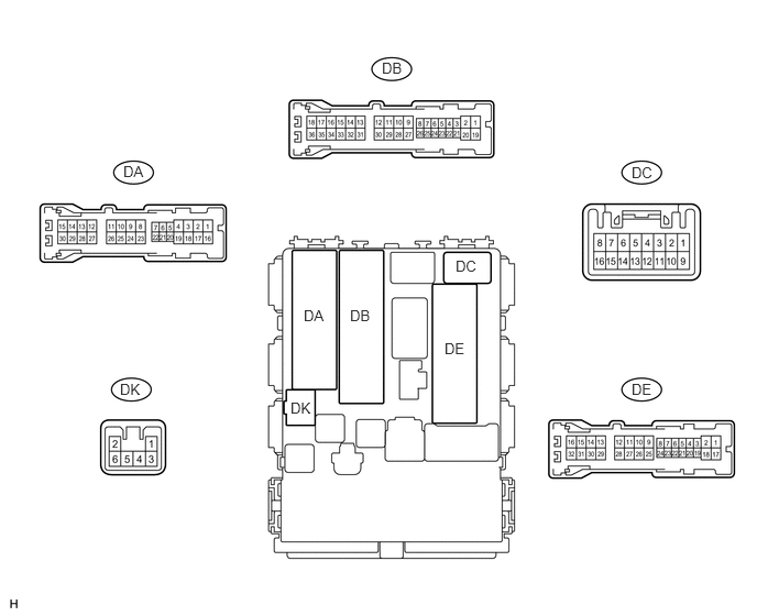
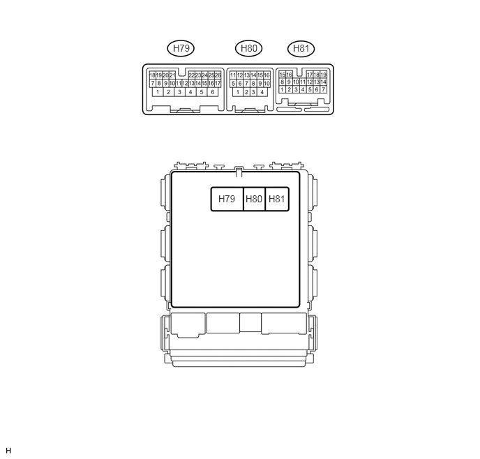
Disconnect the DB, DE, DH and H80 main body ECU connectors.
Measure the voltage and resistance according to the value(s) in the table below.
Terminal No. (Symbol)
Wiring Color
Terminal Description
Condition
Specified Condition
DH-12 (BECU) - Body ground
B - Body ground
Battery power supply
Always
11 to 14 V
DE-28 (GND1) - Body ground
W-B - Body ground
Body ground
Always
Below 1 Ω
H80-4 (GND2) - Body ground
W-B - Body ground
Body ground
Always
Below 1 Ω
If the result is not as specified, there may be a malfunction on the wire harness side.
Reconnect the DB, DE and H80 main body ECU connectors.
Measure the voltage according to the value(s) in the table below.
Terminal No. (Symbol)
Wiring Color
Terminal Description
Condition
Specified Condition
DK-2 (ILE) - DE-28 (GND1)
W - W-B
Interior light signal
Interior light on
Below 1 V
Interior light off
11 to 14 V
H79-2 (FSPT) - DE-28 (GND1)
W-B - W-B
No. 1 interior illumination light signal
No. 1 interior illumination light illumination on
Below 1 V
No. 1 interior illumination light illumination off
11 to 14 V
H79-8 (LCTY) - DE-28 (GND1)
SB - W-B
Rear door courtesy light switch signal
(Rear left door)
Rear left door open
Below 1 V
Rear left door closed
11 to 14 V
DA-21 (DCTY) - DE-28 (GND1)*1
DC-6 (DCTY) - DE-28 (GND1)*2
W - W-B*1
BR - W-B*2
Front door courtesy light switch signal
(Driver side door)
Driver side door open
Below 1 V
Driver side door closed
11 to 14 V
DE-19 (RCTY) - DE-28 (GND1)
LG - W-B
Rear door courtesy light switch signal
(Rear right door)
Rear right door open
Below 1 V
Rear right door closed
11 to 14 V
DE-20 (PCTY) - DE-28 (GND1)*1
DA-24 (PCTY) - DE-28 (GND1)*2
BR - W-B*1
W - W-B*2
Front door courtesy light switch signal
(Front passenger side door)
Front passenger side door open
Below 1 V
Front passenger side door closed
11 to 14 V
DA-7 (BCTY) - DE-28 (GND1)
LG - W-B
Back door courtesy light switch signal
Back door open
Below 1 V
Back door closed
11 to 14 V
H79-19 (DOMR) - DE-28 (GND1)*1
H79-3 (DOMR) - DE-28 (GND1)*2
P - W-B
Battery saving control (interior light auto cut function) signal
Battery saving control (interior light auto cut function) operating
11 to 14 V
Battery saving control (interior light auto cut function) not operating
Below 1 V
H79-25 (LSWD) - DE-28 (GND1)
Y - W-B*1
LG - W-B*2
Front door unlock detection switch signal
(Driver side door)
Driver side door locked
Pulse generation
Driver side door unlocked
Below 1 V
H79-10 (LSWP) - DE-28 (GND1)
LG - W-B
Front door unlock detection switch signal
(Front passenger side door)
Front passenger side door locked
Pulse generation
Front passenger side door unlocked
Below 1 V
H81-10 (LSR) - DE-28 (GND1)
Y - W-B
LH and RH side rear door unlock detection switch signal
LH and RH side rear door locked
Pulse generation
LH or RH side rear door unlocked
Below 1 V
*1: for LHD
*2: for RHD