NAVIGATION SYSTEM(for HDD) Reverse Signal Circuit
| DTC Code | DTC Name |
|---|---|
| Reverse Signal Circuit |
DESCRIPTION
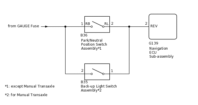
The navigation ECU sub-assembly a reverse signal from the park/neutral position switch assembly*1 or back-up light switch assembly*2 to use for adjusting the vehicle position on the display.
*1: except Manual Transaxle
*2: for Manual Transaxle
WIRING DIAGRAM
PROCEDURE
CHECK VEHICLE SIGNAL (OPERATION CHECK)
-
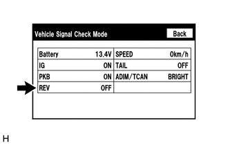
Enter the "Function Check/Setting I" mode and select "Vehicle Signal".
Check that the display changes between ON and OFF according to the shift lever position.
OK
Shift Lever Position
Display
R
ON
Except R
OFF
Tip:This display is updated once per second. As a result, it is normal for the display to lag behind the actual shift lever position.
Result
Proceed to
OK
NG
-
CHECK NAVIGATION ECU SUB-ASSEMBLY (REVERSE SIGNAL)
-
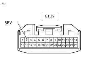
*a
Front view of wire harness connector
(to Navigation ECU Sub-assembly)
Disconnect the navigation ECU sub-assembly connector.
Measure the voltage according to the value(s) in the table below.
Standard Voltage
Tester Connection
Switch Condition
Specified Condition
G139-2 (REV) - Body ground
Ignition switch ON, shift lever in R
11 to 14 V
G139-2 (REV) - Body ground
Ignition switch ON, shift lever any position other than in R
Below 1 V
Result
Proceed to
OK
NG (except Manual Transaxle)
NG (for Manual Transaxle)
NG (for Manual Transaxle) CHECK HARNESS AND CONNECTOR (NAVIGATION ECU SUB-ASSEMBLY - BACK-UP LIGHT SWITCH ASSEMBLY)Click here
-
CHECK HARNESS AND CONNECTOR (NAVIGATION ECU SUB-ASSEMBLY - PARK/NEUTRAL POSITION SWITCH ASSEMBLY)
Disconnect the G139 navigation ECU sub-assembly connector.
Disconnect the B36 park/neutral position switch assembly connector.
Measure the resistance according to the value(s) in the table below.
Standard Resistance
Tester Connection
Condition
Specified Condition
G139-2 (REV) - B36-2 (RL)
Always
Below 1 Ω
G139-2 (REV) - Body ground
Always
10 kΩ or higher
Result
Proceed to
OK
NG
NG REPAIR OR REPLACE HARNESS OR CONNECTOR
CHECK HARNESS AND CONNECTOR (PARK/NEUTRAL POSITION SWITCH ASSEMBLY - BATTERY)
-
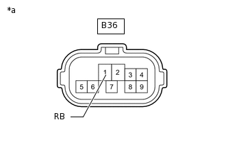
*a
Front view of wire harness connector
(to Park/Neutral Position Switch Assembly)
Disconnect the park/neutral position switch assembly connector.
Measure the voltage according to the value(s) in the table below.
Standard Voltage
Tester Connection
Switch Condition
Specified Condition
B36-1 (RB) - Body ground
Ignition switch ON
11 to 14 V
Result
Proceed to
OK
NG
OK REPLACE PARK/NEUTRAL POSITION SWITCH ASSEMBLY
NG REPAIR OR REPLACE HARNESS OR CONNECTOR
-
CHECK HARNESS AND CONNECTOR (NAVIGATION ECU SUB-ASSEMBLY - BACK-UP LIGHT SWITCH ASSEMBLY)
Disconnect the G139 navigation ECU sub-assembly connector.
Disconnect the B35 back-up light switch assembly connector.
Measure the resistance according to the value(s) in the table below.
Standard Resistance
Tester Connection
Condition
Specified Condition
G139-2 (REV) - B35-1
Always
Below 1 Ω
G139-2 (REV) - Body ground
Always
10 kΩ or higher
Result
Proceed to
OK
NG
NG REPAIR OR REPLACE HARNESS OR CONNECTOR
CHECK HARNESS AND CONNECTOR (BACK-UP LIGHT SWITCH ASSEMBLY - BATTERY)
-
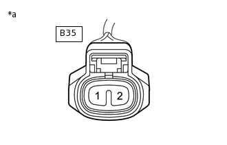
*a
Front view of wire harness connector
(to Back-up Light Switch Assembly)
Disconnect the back-up light switch assembly connector.
Measure the voltage according to the value(s) in the table below.
Standard Voltage
Tester Connection
Switch Condition
Specified Condition
B35-2 - Body ground
Ignition switch ON
11 to 14 V
Result
Proceed to
OK
NG
OK REPLACE BACK-UP LIGHT SWITCH ASSEMBLY
NG REPAIR OR REPLACE HARNESS OR CONNECTOR
-