SFI SYSTEM, Diagnostic DTC:P0013, P0023
| DTC Code | DTC Name |
|---|---|
| P0013 | Camshaft Position "B" Actuator Circuit / Open (Bank 1) |
| P0023 | Camshaft Position "B" Actuator Circuit / Open (Bank 2) |
DESCRIPTION
Refer to P000B Click here.
| DTC No. | DTC Detection Condition | Trouble Area |
|---|---|---|
| P0013 | Oil control valve current is less than 0.306 A for exhaust camshaft circuit for 2 seconds or more (bank 1). (1 trip detection logic) |
|
| P0023 | Oil control valve current is less than 0.306 A for exhaust camshaft circuit for 2 seconds or more (bank 2). (1 trip detection logic) |
|
MONITOR DESCRIPTION
This DTC is designed to detect open or short in the camshaft timing oil control valve (for exhaust camshaft) circuit. If the camshaft timing oil control valve's duty-cycle is excessively high or low while the engine is running, the ECM will illuminate the MIL and store the DTC.
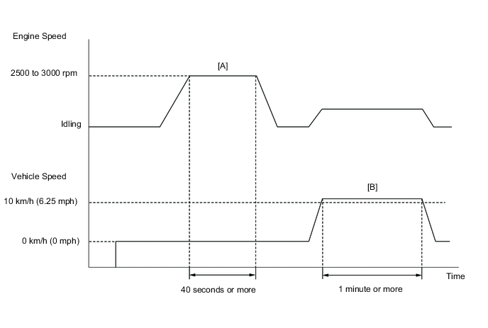
CONFIRMATION DRIVING PATTERN
-
-
Connect the GTS to the DLC3.
-
Turn the ignition switch to ON and turn the GTS on.
-
Clear DTCs (even if no DTCs are stored, perform the clear DTC operation) Click here.
-
Turn the ignition switch off and wait for at least 30 seconds.
-
Turn the ignition switch to ON and turn the GTS on.
-
Start the engine and warm it up until the engine coolant temperature reaches 75°C (167°F) or higher.
-
With the vehicle stationary, depress the accelerator pedal and maintain an engine speed of between 2500 and 3000 rpm for 40 seconds or more [A].
-
Drive the vehicle at 10 km/h (6.25 mph) or more for 1 minute or more [B].
CAUTION:
When performing the confirmation driving pattern, obey all speed limits and traffic laws.
-
Enter the following menus: Powertrain / Engine / Trouble Codes.
-
Read pending DTCs.
Tech Tips
-
If a pending DTC is output, the system is malfunctioning.
-
If a pending DTC is not output, perform the following procedure.
-
-
Enter the following menus: Powertrain / Engine / Utility / All Readiness.
-
Input the DTC: P0013 or P0023.
-
Check the DTC judgment result.
GTS Display Description NORMAL
-
DTC judgment completed
-
System normal
ABNORMAL
-
DTC judgment completed
-
System abnormal
INCOMPLETE
-
DTC judgment not completed
-
Perform driving pattern after confirming DTC enabling conditions
N/A
-
Unable to perform DTC judgment
-
Number of DTCs which do not fulfill DTC preconditions has reached ECU memory limit
Tech Tips
-
If the judgment result shows NORMAL, the system is normal.
-
If the judgment result shows ABNORMAL, the system has a malfunction.
-
-
If the test result is INCOMPLETE or N/A and no DTC is output, perform a universal trip and check for permanent DTCs Click here.
Tech Tips
-
If a permanent DTC is output, the system is malfunctioning.
-
If no permanent DTC is output, the system is normal.
-
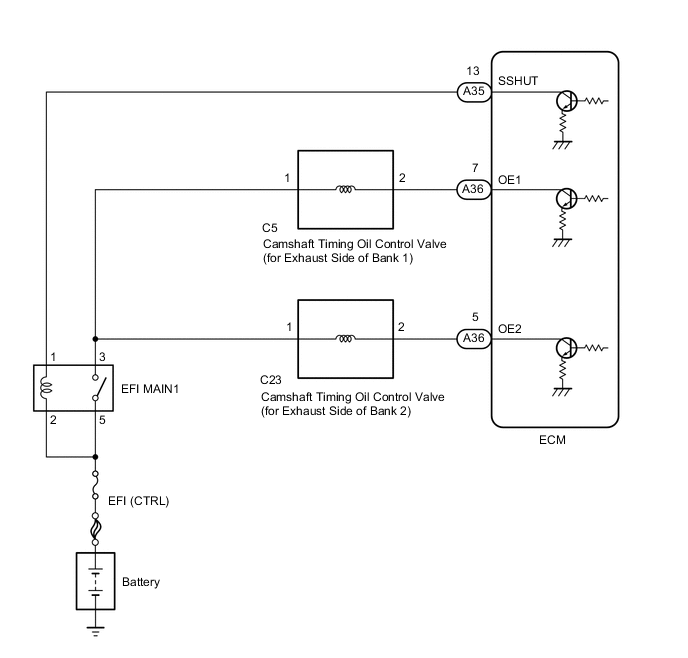
WIRING DIAGRAM
CAUTION / NOTICE / HINT
Tech Tips
-
If DTC P0013 is displayed, check the exhaust camshaft circuit for the right bank VVT system (bank 1).
-
If DTC P0023 is displayed, check the exhaust camshaft circuit for the left bank VVT system (bank 2).
-
Bank 1 refers to the bank that includes the No. 1 cylinder*.
*: The No. 1 cylinder is the cylinder which is farthest from transmission.
-
Bank 2 refers to the bank that does not include the No. 1 cylinder.
-
Read freeze frame data using the GTS. The ECM records vehicle and driving condition information as freeze frame data the moment a DTC is stored. When troubleshooting, freeze frame data can help determine if the vehicle was moving or stationary, if the engine was warmed up or not, if the air fuel ratio was lean or rich, and other data from the time the malfunction occurred.
PROCEDURE
-
READ DTC OUTPUT
-
Connect the GTS to the DLC3.
-
Turn the ignition switch to ON.
-
Turn the GTS on.
-
Clear the DTC after recording the freeze frame data and DTC.
-
Turn the ignition switch off.
-
Start the engine and allow the engine to idle.
-
Enter the following menus: Powertrain / Engine / Trouble Codes.
-
Read DTCs.
Result Result Proceed to DTC P0013 or P0023 is output A DTC is not output B
B 
CHECK FOR INTERMITTENT PROBLEMS Click here
A 
-
-
INSPECT CAMSHAFT TIMING OIL CONTROL VALVE (FOR EXHAUST CAMSHAFT)
-
Inspect the camshaft timing oil control valve (for exhaust camshaft) Click here.
NG
REPLACE CAMSHAFT TIMING OIL CONTROL VALVE (FOR EXHAUST CAMSHAFT) Click here
OK
-
-
CHECK TERMINAL VOLTAGE (POWER SOURCE OF CAMSHAFT TIMING OIL CONTROL VALVE)
-
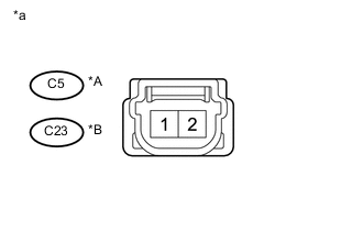
Text in Illustration *A Bank 1 *B Bank 2 *a Front view of wire harness connector
(to Camshaft Timing Oil Control Valve)
Disconnect the camshaft timing oil control valve (for exhaust camshaft connector).
-
Turn the ignition switch to ON.
-
Measure the voltage according to the value(s) in the table below.
Standard Voltage Tester Connection Condition Specified Condition C5-1 - Body ground Ignition switch ON 11 to 14 V C23-1 - Body ground Ignition switch ON 11 to 14 V
NG 
INSPECT RELAY (EFI MAIN1) Click here
OK
-
-
CHECK HARNESS AND CONNECTOR (CAMSHAFT TIMING OIL CONTROL VALVE - ECM)
-
Disconnect the camshaft timing oil control valve (for exhaust camshaft) connector.
-
Disconnect the ECM connector.
-
Measure the resistance according to the value(s) in the table below.
Standard Resistance (Check for open) Tester Connection Condition Specified Condition A36-7 (OE1) - C5-2 Always Below 1 Ω A36-5 (OE2) - C23-2 Always Below 1 Ω Standard Resistance (Check for short) Tester Connection Condition Specified Condition A36-7 (OE1) or C5-2 - Body ground Always 10 kΩ or higher A36-5 (OE2) or C23-2 - Body ground Always 10 kΩ or higher
OK
REPLACE ECM Click here
NG
REPAIR OR REPLACE HARNESS OR CONNECTOR
-
-
INSPECT RELAY (EFI MAIN1)
-
Inspect EFI MAIN1 relay Click here.
NG
REPLACE RELAY (EFI MAIN1)
OK
-
-
CHECK HARNESS AND CONNECTOR (CAMSHAFT TIMING OIL CONTROL VALVE - EFI MAIN1 RELAY)
-
Disconnect the ECM connector.
-
Remove the EFI MAIN1 relay from the engine room relay block assembly.
-
Measure the resistance according to the value(s) in the table below.
Standard Resistance (Check for open) Tester Connection Condition Specified Condition EFI MAIN1 relay terminal 3 - C5-1 Always Below 1 Ω EFI MAIN1 relay terminal 3 - C23-1 Always Below 1 Ω Standard Resistance (Check for short) Tester Connection Condition Specified Condition EFI MAIN1 relay terminal 3 or C5-1 - Body ground Always 10 kΩ or higher EFI MAIN1 relay terminal 3 or C23-1 - Body ground Always 10 kΩ or higher
OK
CHECK ECM POWER SOURCE CIRCUIT Click here
NG
REPAIR OR REPLACE HARNESS OR CONNECTOR
-