ECD SYSTEM, Diagnostic DTC:P20EE
| DTC Code | DTC Name |
|---|---|
| P20EE | SCR NOx Catalyst Efficiency Below Threshold Bank 1 |
DESCRIPTION
The urea Selective Catalytic Reduction (SCR) system injects urea (NH3) into the catalyst to purify NOx.
After the engine is started, the SCR catalyst is heated up for a short period of time before the urea SCR system is activated.
After the SCR catalyst reaches a temperature appropriate for purifying NOx, the urea pump raises the pressure of the urea solution to approximately 500 kPa, delivering pressurized urea solution from the urea tank assembly to the urea injector set.
The urea injector opens the needle valve according to operation signals sent by the urea pump control ECU. When a catalyst temperature is reached at which NOx expelled from the engine will react with ammonia, engine exhaust gas (NOx) and an optimal quantity of urea solution based on the catalyst temperature are injected from the urea injector set to the mixer. In the mixer, atomized and dispersed urea solution is converted to ammonia through hydrolysis, which reacts with the NOx, rendering it harmless.
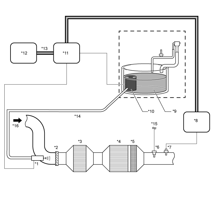
| *1 | Urea Injector Set | *2 | Mixer |
| *3 | SCR Catalyst | *4 | SCR Catalyst |
| *5 | ASC Catalyst | *6 | No. 4 Exhaust Gas Temperature Sensor |
| *7 | Nitrogen Oxides Sensor | *8 | Nitrogen Oxides Sensor Control Unit |
| *9 | Urea Solution | *10 | Urea pump
|
| *11 | Urea Pump Control ECU | *12 | ECM |
| *13 | CAN Communication Line | *14 | Urea Tube with Heater Assembly |
| *15 | to ECM | *16 | Exhaust Gas |
| DTC Detection Drive Pattern | DTC Detection Condition | Trouble Area |
| PM forced regeneration | After comparing the NOx estimated value with the nitrogen oxides sensor value while the urea SCR system is operating, the NOx purification rate is equal to or less than a fixed value. (2 trip detection logic) |
|
When P20EE is output, it may be the result of the following malfunction modes.
-
The urea injector set cannot perform injection as commanded.
-
The concentration of urea solution is thick, or the urea solution has deteriorated.
-
The output of the NOx sensor is offset on the high side.
-
The SCR catalyst has deteriorated.
INSPECTION PROCEDURE
Note
Handling urea solution
-
Wear protective equipment as necessary (protective glasses and gloves).
-
Do not dilute urea solution.
-
If urea solution contacts your eyes or skin, immediately wash the contacted area with a large amount of water and consult a doctor as necessary.
-
If urea solution dries, it deposits a white powder. Also, if urea solution contacts metals such as copper and aluminum for a long period of time, it may promote corrosion. Therefore, if urea solution is spilled, dampen a cloth or other item and wipe it up or rinse the area with cool or warm water.
Handling the urea injector set
-
The urea injector set is a precision instrument. Take necessary precautions for installation and shipping. Do not use the part if it has been struck or dropped.
-
If the urea solution remaining inside the urea injector set dries out, it may become unable to inject urea solution. Therefore, conduct urea tube with heater assembly installation and removal quickly.
-
If the urea solution dries out and deposition occurs, urea may cling to the O-ring of the pipe and cause seal problems. Therefore, clean the urea tube with heater assembly and intake port of the urea injector set with water before attaching them.
-
Perform this procedure in an environment where urea solution will not freeze.
Tech Tips
Read freeze frame data using the GTS. Freeze frame data records the engine condition when malfunctions are detected. When troubleshooting, freeze frame data can help determine if the vehicle was moving or stationary, if the engine was warmed up or not, and other data from the time the malfunction occurred.
PROCEDURE
-
CUSTOMER PROBLEM ANALYSIS
-
Ask the customer whether the vehicle has previously been refilled with something other than AdBlue (conforming to ISO 22241-1) due to a lack of urea solution.
Tech Tips
If the urea solution has been diluted due to the addition of something such as water, purification performance will decrease.
Result Result Proceed to Vehicle has been refilled with something other than AdBlue (conforming to ISO 22241-1) A Except above B
A 
REPLACE UREA SOLUTION Click here
B 
-
-
CHECK DTC OUTPUT
-
Connect the GTS to the DLC3.
-
Turn the ignition switch to ON and turn the GTS on.
-
Enter the following menus: Powertrain / Engine and ECT / Trouble Codes.
-
Read the DTCs.
Result Result Proceed to DTC P20EE is output A DTC P20EE and other DTCs are output* B Tech Tips
*: If codes other than P20EE are output, perform troubleshooting for those DTCs first.
B
GO TO DTC CHART Click here
A
-
-
READ VALUE USING GTS (MAF AND ENGINE SPEED)
-
Connect the GTS to the DLC3.
-
Turn the ignition switch to ON and turn the GTS on.
-
Enter the following menus: Powertrain / Engine and ECT / Data List / MAF and Engine Speed.
-
Start the engine and read the value when 30 seconds has elapsed.
Standard Engine Speed MAF Idling
-
3.0 to 15.0 gm/sec (EGR on)
-
10.0 to 21.0 gm/sec (EGR off)
Running without load (3000 rpm):
-
45.0 to 89.0 gm/sec (EGR on)
-
72.0 to 94.0 gm/sec (EGR off)
-
NG
REPLACE MASS AIR FLOW METER SUB-ASSEMBLY Click here
OK
-
-
CHECK UREA INJECTION PIPES (CHECK DEPOSIT)
Tech Tips
If there are deposits around the urea injector, injection may be inhibited, reducing purification performance.
-
Connect the GTS to the DLC3.
-
Turn the ignition switch to ON and turn the GTS on.
-
Enter the following menus: Powertrain / Engine and ECT / Active Test / Reductant Pump Check (Backward).
-
Perform the Active Test.
-
Enter the following menus: Powertrain / Engine and ECT / Active Test / Reductant Purge.
-
Perform the Active Test.
Tech Tips
Perform the Reductant Purge to draw the urea solution back into the urea tank sub-assembly from the urea injector set.
-
After performing the Active Test, remove the urea injector set from the front exhaust pipe assembly Click here.
Tech Tips
Do not disconnect the urea injector from the urea tube with heater assembly.
-
Check that there is no white matter deposited by urea solution on the connection area of the exhaust pipe.
Tech Tips
After checking for deposits, use a cover, etc., to prevent foreign matter from entering the exhaust pipe.
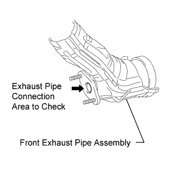
Result Result Proceed to No white matter is deposited by urea solution on connection area of exhaust pipe A White matter is deposited by urea solution on connection area of exhaust pipe B
B
REMOVE DEPOSIT Click here
A
-
-
PERFORM ACTIVE TEST USING GTS (UREA INJECTOR SET OPERATION CHECK)
Tech Tips
If there is a malfunction in the urea injector set, NOx purification performance will be reduced.
-
Use a cover, etc., to prevent foreign matter from entering the exhaust pipe where the urea injector was removed.
-
Enter the following menus: Powertrain / Engine and ECT / Active Test / Reductant Injection Valve.
-
Perform the Active Test and check that operation sounds can be heard from the urea injector set.
OK Sound of urea injector set operation can be heard (a ticking sound). Tech Tips
Even after checking is complete, do not install the urea injector removed from the exhaust pipe yet.
NG
REPLACE UREA INJECTOR SET Click here
OK
-
-
UREA INJECTOR INJECTION STATE CHECK
-
Enter the following menus: Powertrain / Engine / Utility / Reductant Injection Valve Check.
-
Execute the Reductant Injection Valve Check and check the injection condition of the urea injector set.
Tech Tips
-
This test performs operations from urea solution refueling up to injection.
-
The pressure inside the pipe may increase during urea solution refueling, intermittently opening the urea injector set and causing urea solution to leak out.
-
If the urea injector set becomes stuck open during urea solution refueling, once this test starts, intermittent injections will not occur and urea solution will leak out.
-
Urea solution is intermittently injected by the urea injector set.
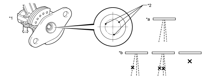
*1 Urea Injector Set *2 Spray Hole *a Urea injector set normal *b Urea injector set abnormal Result Result Proceed to Urea injector set normal A Urea injector set abnormal B Tech Tips
Even after checking is complete, do not install the urea injector removed from the exhaust pipe yet.
-
-
Wash off any matter deposited by the urea solution.
Note
-
Do not damage the urea injector set when washing it.
-
Make sure to leave the connector connected when washing to prevent water from entering via the connector.
-
Sufficiently wipe the area so that no urea solution remains on the flange sealing surface.
-
After completing work, check that 3 streams of liquid are sprayed from the urea injector set.
-
B
REPLACE UREA INJECTOR SET Click here
A
-
-
PERFORM SYSTEM CHECK (NOX SENSOR CHECK)
Tech Tips
When nitrogen oxides sensor output deviates toward the high side, the NOx purification rate decreases.
-
Check that the ignition switch is off.
-
Use an air blow gun to blow air from the mounting hole of the urea injector set toward the nitrogen oxides sensor, expelling remaining NOx in the exhaust pipe.
-
Install the urea injector set Click here.
-
Turn the ignition switch to ON and turn the GTS on.
-
Enter the following menus: Powertrain / Engine and ECT / Utility / NOx Sensor Check.
-
Perform the NOx Sensor Check.
-
Check the output value.
Standard Below approximately 20 ppm Tech Tips
Blowing air expels the NOx in the exhaust pipe. Therefore, if a large volume of NOx is detected, the NOx sensor may be malfunctioning.
NG
REPLACE NITROGEN OXIDES SENSOR Click here
OK
-
-
PERFORM ACTIVE TEST USING GTS (ACTIVATE THE DPF REJUVENATE (PM) )
-
Connect the GTS to the DLC3.
-
Clear the DTCs Click here.
-
Turn the ignition switch off and wait for at least 30 seconds.
-
Turn the ignition switch to ON and turn the GTS on.
-
Start the engine and warm it up until the engine coolant temperature reaches 75°C (167°F) or higher.
-
Enter the following menus: Powertrain / Engine and ECT / Active Test / Activate the DPF Rejuvenate (PM) / Data List / NOx Density B1S1 and SCR Temperature.
-
Perform the Active Test.
Tech Tips
-
Before performing PM forced regeneration control, check that the atmospheric pressure is 94 kPa (705 mmHg, 27.8 in.Hg) or higher, and the ambient temperature is 0°C (0°F) or higher.
-
When PM Accumulation Ratio is too low, Activate the DPF Rejuvenate (PM) cannot be performed. Therefore, rev the engine with no load at 3400 rpm for 5 to 10 minutes to increase PM Accumulation Ratio to 12% or more.
CAUTION:
Be careful of the exhaust pipe and surrounding areas, as they become extremely hot when performing PM forced regeneration control.
Note
If PM forced regeneration control is stopped before it finishes, perform PM forced regeneration control again after repairing malfunctions to complete the procedure.
Tech Tips
-
During PM forced regeneration control the cooling fan motor is forcibly operated and cooling is performed.
-
PM forced regeneration control takes 15 to 40 minutes to finish.
-
The time it takes to complete PM forced regeneration control changes depending on "PM Accumulation Ratio" and vehicle operating conditions.
-
If the value of "Catalyst Differential Press" increases too much during PM forced regeneration control, the fail-safe function activates and PM forced regeneration control is stopped.
-
Perform PM forced regeneration control until the display on the multi-information display turns off.
-
If actions such as depressing the accelerator pedal are performed during PM forced regeneration control, PM forced regeneration control stops. If this occurs, it is necessary to perform PM forced regeneration control again.
-
PM forced regeneration control is not complete until the display on the multi-information display turns off.
-
-
Check "NOx Density B1S1" when the SCR temperature drops to approximately 340°C (644°F).
Standard 50 ppm or less Tech Tips
If the value is above 50 ppm, replace the front exhaust pipe assembly, as it may be expelling ammonia.
NG
REPLACE FRONT EXHAUST PIPE ASSEMBLY Click here
OK 
END
-
-
REMOVE DEPOSIT
-
Clean any deposits from communicating portions of the exhaust pipe.
Tech Tips
After washing, make sure to wipe off the flange surface so that no urea solution remains.
NEXT
PERFORM ACTIVE TEST USING GTS (UREA INJECTOR SET OPERATION CHECK) Click here
-
-
REPLACE FRONT EXHAUST PIPE ASSEMBLY
-
Replace the front exhaust pipe assembly Click here.
NEXT
CONFIRM WHETHER MALFUNCTION HAS BEEN SUCCESSFULLY REPAIRED Click here
-
-
REPLACE MASS AIR FLOW METER SUB-ASSEMBLY
-
Replace the mass air flow meter sub-assembly Click here.
Tech Tips
Before replacing the mass air flow meter sub-assembly, check the connections of the wire harness and connectors. If there is any abnormality, replace or repair the wire harness or connector.
NEXT
CHECK UREA INJECTION PIPES (CHECK DEPOSIT) Click here
-
-
REPLACE NITROGEN OXIDES SENSOR
-
Replace the nitrogen oxides sensor Click here.
NEXT
PERFORM ACTIVE TEST USING GTS (ACTIVATE THE DPF REJUVENATE (PM) ) Click here
-
-
GO TO DTC CHART
-
Diagnose relevant DTCs Click here.
-
Repair any malfunctioning parts indicated by related DTCs.
NEXT
READ VALUE USING GTS (MAF AND ENGINE SPEED) Click here
-
-
REPLACE UREA INJECTOR SET
-
Replace the urea injector set Click here.
NEXT
PERFORM SYSTEM CHECK (NOX SENSOR CHECK) Click here
-
-
REPLACE UREA SOLUTION
-
Connect the GTS to the DLC3.
-
Turn the ignition switch to ON and turn the GTS on.
-
Enter the following menus: Powertrain / Engine and ECT / Active Test / Reductant Pump Check (Backward).
-
Perform the Active Test.
-
Enter the following menus: Powertrain / Engine and ECT / Active Test / Reductant Purge.
-
Perform the Active Test.
Tech Tips
Perform the Reductant Purge to draw the urea solution back into the urea tank sub-assembly from the urea injector set.
-
After performing the Active Test, remove the urea injector set from the urea tube with heater assembly Click here.
Tech Tips
If the urea solution remaining inside the urea injector set dries out, it may become unable to inject urea solution. Therefore, seal the urea injector set with an item such as a cover or rubber cap so that the inside does not dry out.
-
Prepare a bucket or other receptacle for collecting urea solution from the urea tube with heater assembly.
-
Enter the following menus: Powertrain / Engine and ECT / Active Test / Reductant Discharge.
-
Perform the Active Test to drain all the urea solution.
-
After fully draining the urea solution, refill with AdBlue (conforming to ISO 22241-1).
NEXT
PERFORM ACTIVE TEST USING GTS (ACTIVATE THE DPF REJUVENATE (PM) ) Click here
-
-
CONFIRM WHETHER MALFUNCTION HAS BEEN SUCCESSFULLY REPAIRED
-
Connect the GTS to the DLC3.
-
Clear the DTCs Click here.
-
Turn the ignition switch off and wait for at least 30 seconds.
-
Turn the ignition switch to ON and turn the GTS on.
-
Start the engine and warm it up until the engine coolant temperature reaches 75°C (167°F) or higher.
-
Enter the following menus: Powertrain / Engine and ECT / Active Test / Activate the DPF Rejuvenate (PM) / Data List / NOx Density B1S1 and SCR Temperature.
-
Perform the Active Test.
Tech Tips
-
Before performing the Active Test, press the snapshot button and record the data.
-
Before performing PM forced regeneration control, check that the atmospheric pressure is 94 kPa (705 mmHg, 27.8 in.Hg) or higher, and the ambient temperature is 0°C (0°F) or higher.
-
When PM Accumulation Ratio is too low, Activate the DPF Rejuvenate (PM) cannot be performed. Therefore, rev the engine with no load at 3400 rpm for 5 to 10 minutes to increase PM Accumulation Ratio to 12% or more.
CAUTION:
Be careful of the exhaust pipe and surrounding areas, as they become extremely hot when performing PM forced regeneration control.
Note
If PM forced regeneration control is stopped before it finishes, perform PM forced regeneration control again after repairing malfunctions to complete the procedure.
Tech Tips
-
During PM forced regeneration control the cooling fan motor is forcibly operated and cooling is performed.
-
PM forced regeneration control takes 15 to 40 minutes to finish.
-
The time it takes to complete PM forced regeneration control changes depending on "PM Accumulation Ratio" and vehicle operating conditions.
-
If the value of "Catalyst Differential Press" increases too much during PM forced regeneration control, the fail-safe function activates and PM forced regeneration control is stopped.
-
Perform PM forced regeneration control until the display on the multi-information display turns off.
-
If actions such as depressing the accelerator pedal are performed during PM forced regeneration control, PM forced regeneration control stops. If this occurs, it is necessary to perform PM forced regeneration control again.
-
PM forced regeneration control is not complete until the display on the multi-information display turns off.
-
-
Check "NOx Density B1S1" when the SCR temperature drops to approximately 340°C (644°F) according to the recorded data (snapshot).
Standard 50 ppm or less
NEXT
END
-